
R/C Helicopter Hobby in Singapore
|
| Home | Why R/C Helicopter? | How to start? | Setting up | Articles | Flying Lessons | Links | Message Board | For Sale |
contributed by Clarence Boudville
Tail Rotor bell crank shaft Modification.
This modification provides a much stronger shaft, removes slop and allows the bell crank to be removed for servicing.
Items required:- Raptor 30/50 Stock Elevator A-Arm
1.5mm Hex bolt and retaining nut
1.5mm dia washer
Raptor 30/50 plastic ball link
Step 1:- Cut off the carbon bell crank attached to the corner of the gearbox.
Step 2:- Cut 2 pin insert bosses from the Raptor Elevator A-Arm. Cut just in-line with the pin hole. Cut a third boss leaving part of the arm as long as the width of the gearbox top (This will be glued to the top of the gear box and therefore the additional length of the arm provides extra surface for the CA/ Epoxy to bond).
Step 3:- Test fit the bosses on the gear box. (Insert the 1.5 mm bolt and line the boss up to allow the first two bosses to fit to also fit to the side of the gear box. Once this fits, glue the third boss (the one with part of the arm) to the top of the gearbox and line the hole exactly at almost the corner of the gearbox next to where the original carbon used to be and the first two bosses to the side of the gearbox. Use the 1.5mm bolt as for alignment. Allow the glue to set.
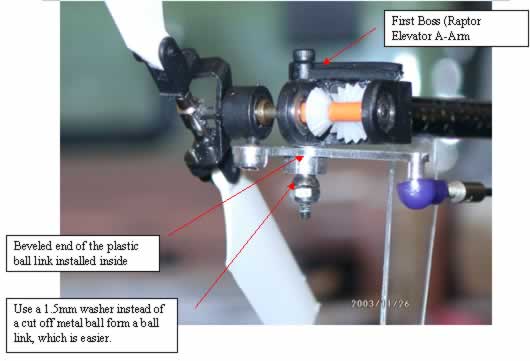
Step 4:- Insert the beveled end of the Raptor ball link into
the top part of the tail bell crank and mark the ball link leveled with the
surface of the bell crank to be cut off.
Next cut of the beveled end of the Raptor ball link and insert this into the
bell crank. (This helps take the slop out of the bell crank for better tail
response).
Step 5:- Insert the 1.5mm dia washer into the bolt already fitted to the bosses. Apply a little CA / Epoxy to the top of the washer where it contacts the gear box. (This provides additional strength). Next insert the previously cutoff beveled end of the ball link into the shaft followed by the bell crank.
Step 6: Insert another 1.5mm washer and then the 1.5mm nut and slowly / carefully bolt it down until the bell crank has no more slop but still has free play. Now you are done!
Refer to the photos as a guide.
Tail Rotor Hub Modification
This modification ensures a positive tail rotor hub assembly as opposed to the stock method of CA and breaking away in flight.
Items required:-
1.5mm bolts and retaining nut
Step1:- Insert the 1.5mm bolt into the retaining nut and leave about 2 mm protruding
from the nut. Clamp the nut on to a vice and proceed using a triangular needle
file to file a screwdriver slot on the protruding end. The slot should only
be wide and deep enough to fit a jeweler’s screwdriver that can be inserted
into the threaded part of the tail rotor hub.
Step 2:- Unscrew the nut and let the slotted end sink into the nut hole about 2-3mm. Then saw off the other end of the bolt and file it neatly. There you got your self a very short grub screw. Make another one of this.
Step 3:- Now screw this grub screw into the tail rotor hub
with the hub fixed on the tail shaft. Carefully tighten the grub screw until
the hub is secured. Do the same with the other end. Now fit the tail rotor fin
back and you will notice that the tail fin bolt will now not fully seat. Not
a problem, continue to screw down until the stud protrudes on the inner side
of the tail blade grip but stop just before it touches the blade root. Now back
off the stud by ? turn and check the operation of the tail rotor blade. Now
fit the slider back. You are done.
