The Speaker Guy
Dedicated to Really Cheap Audio Enthusiasts
Low-Cost Satellite Speakers
Initial Design and Box Assembly Finishing and Final Assembly
Machining the Baffles Making  the SpeakerGrills
Initial Design and Box Assembly
Testing and Conclusions
Building the Crossover
Mechanical Drawings
These are a pair of sealed speakers for use as satellites to an existing subwoofer. They are housed in a sealed enclosure, with a 2nd order Linkwitz-Reilly crossover at 3.85kHz. The woofer is Parts Express # 269-469, a 4 in. extended range driver, and the tweeter is Parts Express #279-255, a Pioneer Mylar dome tweeter. Both elements are rated at 15W, both have 91dB sensitivity, and both are shielded. The woofer is a whopping $0.95 each, while the tweeter is $2.95

The objectives of this project are legion:
1 – Replace an existing pair of VERY cheap plastic speakers.
2 – Use my existing inventory. Because the woofer and tweeter were so inexpensive I purchased 8 pieces of each on impulse.
3 – Eliminate (or reduce the size of) the full sheet of ½ in. MDF sitting in my garage. It was in my way.
4 – Provide a very easy and low-cost design for neophyte speaker builders.

Based on the output of Abacus, I will get a very flat response with a sealed 7 liter box. The predicted f3dB is 133 Hz, sufficient for use with a subwoofer.

I used Microsoft Works Spreadsheet to do the volume calculations. Using the 0.6 x 1.0 x 1.6 golden rule dimensions yields a box size of 4.62 x 7.7 x 12.32 inches. I didn’t want to use the weird fractions, so I adjusted to 5 x 7.5 x 12 inches, close enough for me. This gives a box volume of 0.260 ft.^3, compared to the ideal value 0f 0.247 ft. ^3. I figure the slight rounding up will help accommodate the internal speaker volume, which is very minimal.

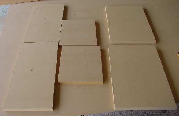
The cabinet is made with 1/2 in. MDF with no internal bracing. All the joints are butt-type and glued with polyurethane glue. Prior to beginning assembly, lay the parts out on the bench and label them for east identification. I used “A” for the baffle and back, “B” for the small top and bottom pieces, and “C” for the two sides. See Figure 1.
Figure 1. All parts laid out
Figure 1. All parts laid out on bench.
Before putting glue on anything, double-check the dimensions of the pieces. In Figure 2 note the length of “C” plus the two thicknesses of “B” equals the length of “A”. Also, the width of “B” is equal to the width of “C”.

Figure 2. Dry run, checking for correct dimensions
To avoid any nails which can nick router bits I chose to simply use masking tape as the preliminary clamps. I placed the baffle piece “A” down on the bench, and glued up the two “B” pieces and the two “C” pieces. By pulling very tight on the masking tape I was able to pull all the joints into alignment. Be very careful that the two pieces “C” are aligned flush with edges of “A” and “B”. There are no dados or internal guides to prevent “C” from slipping inward. Make sure all the joints are well aligned and tightly taped as shown in Figure 3 prior to attaching the final piece “A” on top of the assembly.
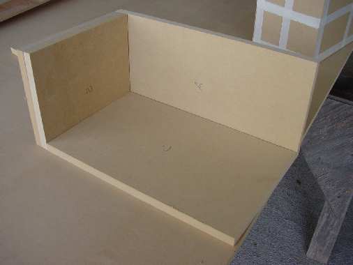
<<Insert Figure 3. Box glue up, inside view>>


Figure 3. Box glue up before adding top
Note that enough glue has been used such that it slightly oozes out of each joint as seen on the inside of the box in Figure 3. I slightly bias the amount of glue I put on each edge such that there is more glue on the inside. This minimizes the amount of sanding to the finished box. If in doubt extra glue can be added to the inside edges just in case.

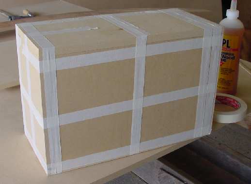
Once you are satisfied that the base is aligned and adequately glued, attach the backside “A” of to the cabinet. Because you can’t inspect the inside of this joint use a liberal amount of glue. Then tape the whole assembly, making sure to pull the masking tape tight across each length. Remember; do not push against either “C” piece because it is unsupported inside the box. If this happens you must partially disassemble the box to realign the side. The finished taped assembly is shown in figure 4.

Figure 4. Box glue up complete

Set the first box aside and repeat the above procedures for the second box. Once this box is done both boxes can be clamped as one unit. Be careful not to exert any sideways force with the clamps. See Figure 5. Now is a good time to go watch the “Battle Bots” marathon on Comedy Central. The boxes will require at least a few hours to dry. If possible leave them alone overnight.

Figure 5. Both boxes taped and clamped
Initial Design and Box Assembly Finishing and Final Assembly
Mechanical Drawings
Machining the Baffles Making  the SpeakerGrills
The Speaker Guy Home Page
Testing and Conclusions
Building the Crossover