
ICL7107 based, 4 channel digital
thermometer
All diference between this schematics and standard 7107 voltmeter is that
LO input of internal amplifier ist floated from ground through R11 and R12.
In this way 7107 becomes a relative positive or negative voltmeter and can
display any signals in ZERO
FULL-SCALE range when the signal have a small variation and a large positive
offset value( like bM135 temperature sensor ).
Here only two digits are used for temperature display, so for 23C, 230...
239 mV can be measured between HI and LO input pins. However another display
digit can be added at A1...G1 pins and tenth of C will be displayed.
For measuring four different temperature signals some logic and analogic
stage must be added at voltmeter section:
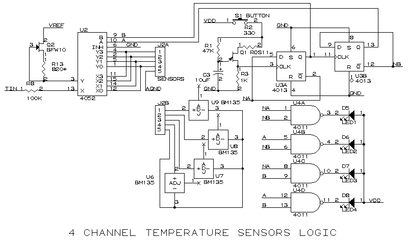
U6 to U9 temperature sensors are biasing under constant current generated
by Q2 and R13 . Q2 running in Z point ( near zero thermal drift ) so constant
current through sensors is total independent from ambient temperature ( this
is a important condition because inside temperature in a car is between -20
to +65 C ). U3 is a two bite counter, clocking pulse come from UJT transistor
Q1 when S1 button is pressed. A binary to zecimal decoder (U4) and four LED's
show wich sensor's temperature is being displayed.
Unfortunately car's have only positive suply, so a negative
one must be generated using a 723 in a self oscillating mode. The internal
reference of 723 is also used for 7107 voltmeter. A voltage doubler rectifier
( C1,C2,D2,D3) obtained -5V for 7107 supply.

The whole schematics is here:

Design and made a reliable PCB for cars needs some profesional aknowledgements and a lot of work, so PCB is not available here. But I can project any PCB's for serious customers.
Back to Vasile's
electronics page