X band radar
detector
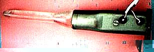
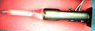
One original Japanese radar detector for X and K band is shown here:
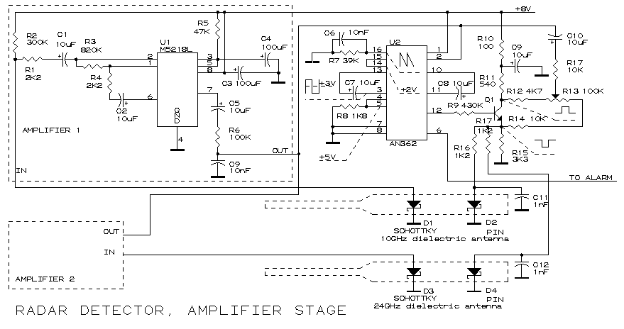
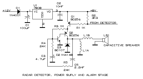
Unfortunately I can't found anywhere on the web a full data sheet of M5218 and AN362. In this schematic U1 is a AC signal amplifier generated by D1 or D3 schottky diodes who acts like a detection diodes. To increase the sensivity of diodes a DC polarization made by R2 is done. Some schottky diodes works better without this polarization. U1 must have a global amplifier factor of about 100,000. U2 is a specialized integrated circuit who must have inside a oscillator, a comparator and a stage who can adjust sensitivity of threshold for comparator ( from R13 ). The oscillator supplies with a square signal both PIN diodes (D2, D4) of antennas. These diodes are a modulator for input microwaves signal detected by Schottky diodes. The voltage level measured here is very small, in tens of micro volts range. A DC coupled amplifier can't handle with some small signals because of offset and temperature drift coefficient of any operational amplifier. The detected and amplified AC signal is mixed with a feedback signal generated by local oscillator with variable phase (modified from R13) and applied to U2 pin2. Inside U2 is probably compared with a reference threshold, the result of comparison starts or not the alarm stage ( when U2 pin 6 signal level is LOW the alarm is ON ). R5 and C5 from alarm stage set the tonality of noise and R3,R4 and C3 the time period between ON and OFF ( about 0.5 seconds ). Using a stabilized power supply is required for suppress all noises made by car engine and other electronics inside the car.
Unfortunately the sensitivity of
this radar detector is poor, only 40...50 meters of detection area can be
achieved.
A better amplifier was developed by me in next
figure:

Here the maximum amplifier coefficient for LM387 was
achieved with a good stability. Some little adjustments can be done from
R2 and R4. This amplifier must be packaged in a iron case to suppress all
noises. A window comparator with two threshold points at 4.5V and 5.5V can
be added at COMPARATOR output, the comparator output is connected to the
alarm stage DETECTOR input. The local oscillator is a gate from U3 Schmitd
trigger.
Dielectric antenna pictures for X band are below: