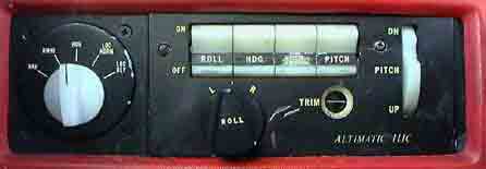
Altimatic III Autopilot is a three axis autopilot which is linked to the HSI. The Display consists of:
1 A rotating Radio Coupler Selector knob (white at far left)
NOTE - when rotating this knob - that it is extremely easy inadvertently to knock the fwd. Right Engine Magneto Switch to the Off Position with the knuckle of he left hand. For Obvious reasons ALWAYS check the Magneto Switch after altering the position of this knob.
2 A row of Mode Selector Rocker Switches "Roll" "Hdg" "Alt" and "Pitch"
3 A Left and Right Roll knob
4 A Trim Needle Indicator in window
5 A White Pitch Trim Adjustment rotating disc with central detente position (just visible)
MODE SELECTOR OPERATION
When engaged (and some or all may be engaged) the Mode Switches have the following effects:
ROLL To engage ROLL mode, Select HDG on the Radio Coupler, then centre the ROLL knob. Then push ROLL rocker switch to ON (ie (Top section in). To turn the aircraft, simply rotate the ROLL knob and the aircraft will effect a roll. Limit angles of bank to 30 degrees. This action merely replicates the action of rotating the yoke on the control column.
HDG To engage Heading (HDG) Mode, (which can only be engaged when ROLL mode rocker switch is set to ON), again Select HDG on the Radio Coupler, then set HSI Hdg Bug to desired heading. Then engage HDG Mode by pressing the HDG rocker switch. The aircraft will then make roll adjustments of up to 20 degrees bank angle to maintain that heading. A change in the Hdg Bug setting will be followed by the Autopilot
PITCH To engage Pitch Mode. First engage ROLL mode by pressing ROLL rocker switch. Then Centre the pitch trim indicator needle using the white pitch command disc. Finally engage PITCH rocker switch. The pitch of the aircraft can then be adjusted up or down by rotating the pitch disc in the direction shown, (which mirrors the pitch trim wheel found on the floor in the PA28 and other aircraft - ie forward = down, back = up). Pitch mode replicates the action of (a) using the manual trim in the ceiling (b) using the electric trim switch on the control column.
ALT (hold) Once you have reached the desired altitude, engaging Altitude Hold mode (by pressing the ALT rocker switch, which again can only be pressed when PITCH switch has been pressed) will keep the aircraft at that altitude. Proper operation requires that you trim the aircraft in Pitch by using the procedure referred to above (ie PITCH Mode). If you don't trim first, engaging Alt Hold Mode will result in the aircraft executing a fugoid path through the air, making large adjustments for errors in trim. NOTE Before disengaging Alt Hold Mode, ensure that the pitch command disc is centered.
RADIO COUPLER OPERATION USING THE HSI DISPLAY
The White Selector Switch can be set to one of five options (from the left) NAV, OMNI, HDG, LOC (Norm), LOC (Rev). Operation of the Radio Coupler is as follows:
1 VOR Navigation - to intercept and track a VOR Radial
NAV mode may be engaged to provide a reduced VOR sensitivity for tracking weak or noisy VOR signals. It should only be engaged when the aircraft is well established on course.
2 ILS - LOC (Front Course) - To intercept and track inbound to localiser
3 ILS (Back Course)
4 COUPLED APPROACH OPERATIONS
5 ILS - FRONT COURSE APPROACH WITH GLIDESLOPE CAPTURE
NOTE - Glide Slope Coupler will not automatically decouple from Glide Slope. Decoupling may be accomplished by
YOU MAY ONLY ATTEMPT COUPLED APPROACHES AND GLIDESLOPE CAPTURE WHEN A SAFETY PILOT IS PRESENT OR WHEN YOU HAVE BEEN CHECKED OUT ON AUTOPILOT OPERATIONS