Very often power tools run too fast for cutting plastics and lack speed controls. These can be added for less than $ 5, if enough space can be found inside their housings. An alternative is to add an external box with an outlet into which any tool can be plugged. The basic circuit requires few parts and "minimal" space.
Note: Adjust brightness and contrast for optimum viewing.
SIMPLE TRIAC MOTOR SPEED CONTROL
| TR1: Triac XX Amp, 200 V. min.
D1: Diac. R1, R2, R3: Resistor 1 K, 1/2 W. C1, C2, C3: Non-polar Capacitor .1 µ f, 200 V min. VR1: Potentiometer 100 K, 1/2 W. |
The theory behind the operation can be found by searching the Net under triac, light dimmers or motor speed controls. Although not necessary with some motors, R1 and the snubber circuit, R3 and C3, reduce false triggering caused by pulses from brush arcing and other commutation.
For long term, trouble free operation. triac current should be at least twice the motor rating. The tab should be polished and mounted on the largest heat sink that will fit, using heat sink compound.
For a one time project, it was not worth the effort to make a PCB that might not fit. Fabricated first, a Micro-Mark table saw circuit was hard wired point to point in free space. Two 510 ohm resistors were soldered in series to make 1 k, since almost 200 were on hand. Provisions for pot mounting were already cast into housing. The triac and heat sink were screwed to an available PCB standoff.

Note: Adjust brightness and contrast for optimum viewing.
POINT-TO-POINT HARDWIRED
A #10 crimp lug makes a handy terminal for all leads at the bottom.
Finding some perf-board, this was used to hold components in a cut-off chopper. The circuit can easily fit in a .6" x 1.2" space.

Note: Adjust brightness and contrast for optimum viewing.
COMPONENTS ON PERF-BOARD
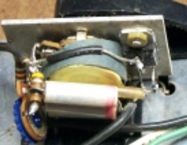
Some Dremel foot controls were found at a bargain price, but were fused at 5 A with an 8 A triac. Since my lathe is rated at 5 A, the triacs were replaced with 12 A and the unit fused for 10 A. In most cases, just replacing the triac and fuse will suffice, but motors vary in characteristics and the range limits may not match. Since the potentiometer is turned by a curved rack and pinion set up, it rotates only about 70% of the full range. There is a trim pot in parallel with the speed pot to permit range adjustment.

Note: Adjust brightness and contrast for optimum viewing.
DREMEL FOOT SPEED CONTROL
| R1: 10 K
VR1: 200 K, trim-pot VR2: 100 K C1, C2: .15 µf |
With both pots set at maximum, there is 210 K in parallel with 100K yielding about 68 K. This may not be enough to stop some motors when the pedal is released. The easiest way to increase the R-C time constant is to solder about a .1 µf capacitor in parallel with each of those on the board. Then the trim pot can be adjusted to the desired setting.
 CAUTION:Opening the case, while plugged in, will expose you to full
line voltage and possible deadly shock.
CAUTION:Opening the case, while plugged in, will expose you to full
line voltage and possible deadly shock.

Note: Adjust brightness and contrast for optimum viewing.
NEW VERSION W/ PCB
Unsoldering triac leads permits swinging PCB for access to heat sink screw. Trimmer and any additional capacitors are mounted on trace side of board.
The older design had point-to-point wiring, so the triac is easier to change. R2 is omitted in the design.
Note: Adjust brightness and contrast for optimum viewing.
BACK TO METHODS INDEX
BACK TO POWER SAWS
