Many tedious tasks associated with these details can be simplified through the use of the right tools. Drilling or shaping templates are provided with some kits and other templates, jigs and fixtures can be fabricated or devised easily.
Before delving into selecting tools or making aids, a little research on the prototype practices is advisable, using text, drawings and photographs. In most cases, dimensions are not given, but eyeballing can yield a believable result. In the Car Builders Cyclopedia, AAR Safety Appliances plates cover minimum and preferred dimensions for handholds, ladders, steps, platforms, running boards and external brake gear. Mounting and materials are covered in text. As an example, handhold bar stock has a minimum of 5/8" , close to .070 in HO; with no preference. Minimum length is 16" and clearance is 2", with a preferred 2 1/2" (.0287 in HO. A strip of .030" plastic could make a good spacer. Specific dimensions and locations are best found from photos and drawings of the prototype.
Drilling templates can help prevent many mistakes requiring filling and redrilling. Plastic works well, but metal is more durable for repeated operations. The hard parts is sizing to fit and laying out the holes. But it is better to err on a scrap sheet than on the model. Guides may be added to aid alignment, but limit versatility in location.
Bending jigs for odd grab irons and handrails, including curved, vee and ell shapes, are often supplied, some of which may also provide drilling templets. Using ideas based on these others can be made.
Note: Adjust brightness and contrast for optimum viewing.
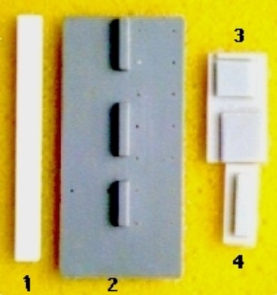
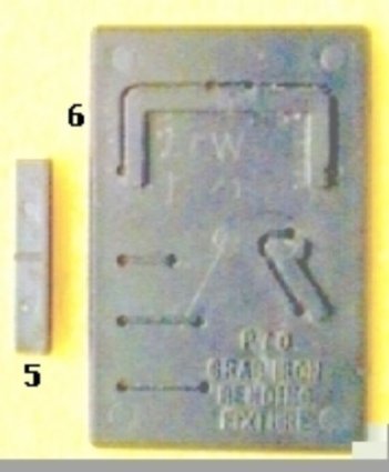
JIGS FROM KITS
- Spacer strip.
- Back of grab drilling template showing aligner.
- Bending jig for el and long long grabs.
- Step bending jig
- Step leg drilling template with aligners.
- Eastern carworks (Alco) combination passenger car handrail bending jig and drilling template.
NOTE: Particularly in harder metals, bending generates heat, which tends to temper or harden the bend. Sharp or repeated bending agrevates the condition and may lead to breakage. Bend slowly to prevent heat build up. In extreme cases, annealing may be required, by heating with a torch and cooling slowly. In music wire and other springy metals, angles or curves, will require finish bending due to the tendency to spring back toward the original shape.
Long nose pliers, with straight serrations perpendicular to the jaw centerline, make excellent flat bottom, "U" shaped, grab iron bending jigs. The tapered jaws permit almost any size. Select the correct serration with calipers, set to length using mounting holes. Mark it for reference, place the wire in it and squeeze to hold. Bend with fingers. Then squeeze the legs, against the jaw, with another pair of smooth pliers to sharpen the bends. The right angles may not be perfect, but they can be corrected easily after removing from "jig".

Note: Adjust brightness and contrast for optimum viewing.
LONG NOSE PLIERS USED TO BEND STRAIGHT U SHAPED GRABS
Note: Leave the legs longer then required and clip close to inside of wall after gluing with ACC. If necessary finish them flush with a diamond file. For easier insertion one leg should be longer than the other. An Evergreen strip of the correct thickness can be used to set spacing from wall. Al Westerfield suggests twisting legs in opposite directions to level.
For longer grabs and handrails, on larger scales, electronic component lead bending jigs work well. Less flexible, inexpensive solid versions are readily available, ranging from .4" to 1.9" in .05" increments. Both are double sided to center various sized components.

Note: Adjust brightness and contrast for optimum viewing.
FIXED ELECTRONIC LEAD BENDERS
For those longer than about .4", adjustable lead benders provide a point and bend operation. Used for bending leads of components mounted in predrilled, printed circuit board holes; the points are adjusted to fit the holes with the thumbwheel by the worm follower. Then the leads are clamped in slots by a trigger lever for bending. No measuring is required.

Note: Adjust brightness and contrast for optimum viewing.
ADJUSTABLE ELECTRONICS LEAD BENDER
Drop grabs of several sizes are available from a few sources, but most drop too far (about 4 to 7 inches in HO). From compendium drawings and handhold end view photos they appear to drop about the same distances as the clearance, which is closer to 2 1/2".
Note: Adjust brightness and contrast for optimum viewing.
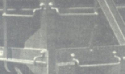
PRR HOPPER DROP GRABS ON LADDERS AND END SILL
How prototype drops are bent.
The improved effect is clear on a Funaro & Camerlengo gondola before painting.


Note: Adjust brightness and contrast for optimum viewing.
DROP GRAB ON F & C PRR GR GONDOLA
Bending a quantity of identical drop grab irons, to this small dimension or others, not available, can be very difficult. To simplify the process, bending jigs can be fabricated to make any size, using 2 K & S .035" thick brass strips. Adding a screw to clamp them together, helps with alignment.

Note: Adjust brightness and contrast for optimum viewing.
DROP GRAB IRON BENDING JIG BOTTOM PLATE

Note: Adjust brightness and contrast for optimum viewing.
DROP GRAB IRON BENDING JIG BOTTOM PLATE LAYOUT
Note: Adjust brightness and contrast for optimum viewing.
ENLARGED VIEW
Initial scribe lines at end are in yellow. End view shows only the shape of variable length jig.
Plastic should not be used for shallow drops or wire stiff enough to avoid finger crunching, since there is too much give and stress may distort or break narrow lip. Brass is more durable. Select a .065"thick strip, wide enough to handle the longest grab to be made and cut a vee slot across the end at a distance just slightly more than the desired drop, since the bends will be slightly less than 90 degrees. About .030" yields a 2 1/2" drop in HO. The depth should be about the diameter of the smallest wire used. The method will depend on your tools. A vee, ala a vee block, is the best choice, but any slot that will hold several diameters securely will do. If making by hand, it might be easier to cut slot slightly farther in from end and test. Excess can be removed with file or other means,
To avoid eye strain, apply Dykem or use a felt tip marker and with calipers, scribe the cross line first, then scribe the (minimum) grab length lines past the original line.
Although I used a vee tipped cutter in a vertical mill; a rotary tool in a drill press, a fine jeweler's 's saw with miter box or, if you are really steady, a slitting saw in a rotary tool could be used to cut the cross groove. By hand, successive scribing, against a securely clamped, straight edge with a sharp tool, such as a vee point dental pick, will work tediously.
Dependent on your preferences, the next step has choices. If you are only bending one length, just two groves are needed for leg clearance, At the original depth and the distance required. The cuts may cross the first groove without reducing the effectiveness of the jig. More cuts may be added for other lengths later.
Although it requires a milling process, a continuously variable length jig can be made by removing the two end rectangles at groove depth. The finished end shape is shown in the drawing. If cutters are round, the minimum length cuts must cross the first groove to achieve a square corner clearance.
Place, align and clamp a second strip on the first. Drill a tap diameter hole clear through both. The distance is not critical, but the screw should be able to apply pressure on the inserted grabs. Separate and enlarge the hole in the cover plate to clearance diameter and tap the bottom plate hole.
Align sides and finished ends, screw down securely, then cut both to a length, long enough to clamp in a vise for stiff wire cases. Truing the end will make alignment easier by holding against a flat surface while tightening. Working with longer strips, during and after assembly, makes all clamping much easier.
Insert and clamp U grab in jig. Bend legs carefully and slowly toward bottom plate. Tap lightly with hammer, if sharper bends are desired. If U section is twisted from 90 degrees, correct by holding leg and drop with pliers.
If after testing, the angle of the drop is objectionably greater than 90 ° due to spring-back in harder brass or steel wire; the bottom plate bending angle can be carefully beveled to a few degrees less than 90 to compensate.
Avoiding kinks while bending curves can be very tricky. The form should be of a slightly smaller radius than the desired curve to compensate for spring back. Bending should proceed by gradually rolling or wrapping around the form.
For smaller odd curves and loops in handrails and piping, various sized, jeweler's, chain (round) nose or rosary pliers can bend almost any radius. Larger sizes are commonly used by electricians to bend wire loops for connections. Some types are tapered or stepped, while others are specialized for odd shapes.

Note: Adjust brightness and contrast for optimum viewing.
SOME SPECIAL BENDING PLIERS
- Small round nose, chain or rosary.
- Larger radius. Jaws: Convex left_Concave right.
- Curved U die type w/ wire positioning notches. Jaws: Male left_Female right.
- Stepped chain. Jaws: round left_concave right. (KaDee).
- Combination fine chain & flat. Jaws: chain, flat & notches left_flat serrated opposite chain to guide wire, smooth w/ large notch.
Based on a common geometry axiom, the 3 contact point, bending technique, ala KaDee, is great for adjusting coupler trip pins (air hoses), but it will not produce smooth radii. For the originally intended use, the curved jaw should press wire totally into the concaved to obtain smooth arcs.
Often wire comes in coils or on spools, which form a decided curvature. Sometimes softer, short lengths can be straightened with flat pliers or reverse drawing on a curved surface. Even fingers may suffice. For longer lengths, one end is clamped in a vise and the other is given a good yank with pliers. The stretching stress and resultant heat will very often remove any kinks.
Larger curves can be rolled around almost any cylindrical object by hand. Pin and roller jigs are often used, but require experimentation to obtain the correct radius. Wire is drawn through the pins to curve it. Pin spacing determines the curvature. Fixed pins are limited in range, while adjustables can be set to the desired radius.

Note: Adjust brightness and contrast for optimum viewing.
SIMPLE BENCH MOUNT PIN TYPE JIG W/ SLOTS AND ANGLES.
Two of the outer pins can be moved to open hole to change distance and curvature. The rectangular notches can be used to form U steps as covered below.
In the early days of HO, rail was a lot stiffer and had to be pre-curved before laying. Mounted on bushings, the free turning wheels ease drawing rail through, while pressing on the web. The adjustable wheel has a one wing nut to avoid interference. With modified grooved wheels, it is an excellent wire bender.

Note: Adjust brightness and contrast for optimum viewing.
ADJUSTABLE DEAN DOWNER RAIL CURVING JIG.
Commonly used by model airplane buffs to bend music wire for struts, push rods, etc., special bending jigs (tools) are very helpful.

Note: Adjust brightness and contrast for optimum viewing.
WIRE BENDER SET.
Even tubing can be curved, without kinks, using K & S, coiled spring type jigs, intended for bending model airplane fuel lines. Softer copper bends much easier than brass or aluminum. Larger sizes should be annealed frequently to soften. An older method is to pack with fine sand or other granulated substance to prevent crushing kinks.
Note: Adjust brightness and contrast for optimum viewing.
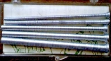
MODEL TUBING BENDER SET W/ 1/16, 3/32, 1/8, 5/32 & 3/16 SIZES.
Steps present their own problems, since the prototype are usually fabricated from strap or flat bar stock and legs may have various shapes. Some may have twisted or bent legs for mounting, additional round or flat rungs plus rear braces that must be positioned. Ladders present similar problems. Over the years many have been offered in metal or plastic, but some were bulky and the thinner plastic versions are very fragile. Jigs, or more often dies, help ease their fabrication.
For "U" shapes, duck nose pliers could be used ala grab irons above, if the jaw taper is very slight. In a pinch, channel and a rectangular strip can used as a die by either pressing or tapping with a hammer.
For winged legs that fasten to a bottom surface, a die should be made from bar stock with a notched female and a tee shaped male.
For handrails, railing, fencing, stairways, ladders and catanry specialized jigs can be fabricated from non- bondable, scrap wood, plastic or metal, dependent on the bonding agent. Quicky assembly jigs can be made using T pins and hold down disks on template underlays, ala model airplanes. More complex jigs can be cut in or built up from any material to hold parts in alignment. Clearance should be left around joints to permit bonding agent application and to avoid joining jig to work. Hard wood works well for soldering railing and fencing, but durability is limited by eventual burnout. Since most common solder fluxes do not work well with aluminum, it may be used; but heat conduction may interfere with proper fusion at joint. Acrylics work well with styrene cements without sticking. Using scrap, a little experimentation will yield many combinations.
BACK TO BENDING AND ROLLING
BACK TO TEMPLATES, JIGS AND FIXTURES
