|
Anti-aliasing
|
If you look closely and critically at lines drawn on the screen, particularly lines that are nearly horizontal or nearly vertical, they may appear to be jagged. The screen is a grid of pixels and the line is approximated by lighting spans of pixels on that grid. The jaggedness is called aliasing; examples of aliased lines are shown in Figure 4.5(a). Anti-aliasing techniques reduce the jaggedness, as shown in Figure 4.5(b), by partially coloring neighbouring pixels to simulate partial pixel coverage.Figure 4.5 Aliased and anti-aliased lines.
These lines are drawn at a resolution of 50 pixels/inch in order to exaggerate the jagged edges of the aliased lines and highlight the widening and blending in the anti-aliased lines. These lines are examples of the general concepts; if you replicate this drawing on a Voodoo Graphics screen, the results may be different in detail.
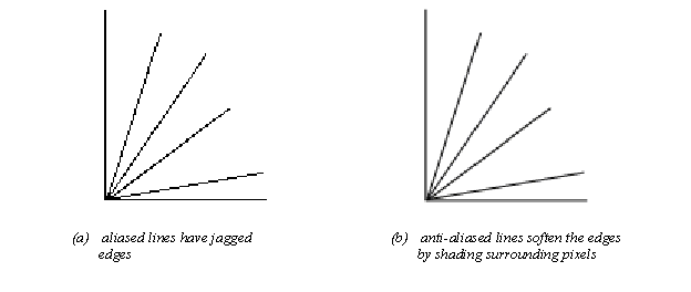
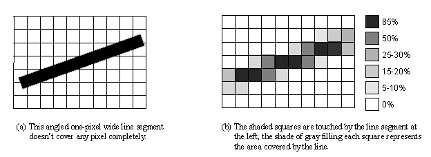
Figure 4.6 shows an angled line segment one pixel wide, superimposed on a pixel grid. Some pixels are almost completely covered by the line, while others have only a small corner involved. Glides anti-aliasing routines compute a coverage value for each pixel and uses that in combination with the source and destination alpha values to blend the pixel color.Figure 4.6 Pixel coverage and lines.
Glide draws anti-aliased points, lines, triangles, and polygons by setting up the alpha iterator so that it represents pixel coverage. You must correctly configure the alpha combine unit (discussed in detail in Chapter 6) and enable alpha blending before using any of the anti-aliased drawing commands. The code segment in details the proper sequence of Glide commands that must precede the actual anti-aliased drawing commands. Briefly, you mustCall a grAADraw or guAADraw function.Set the alpha combine unit to produce iterated alpha. Set the alpha blending function. Blending functions are specified for source and destination color components and for source and destination alpha values, and the choice of function depends on whether the scene will be rendered front to back or back to front. Set the alpha value for each vertex. The chosen alpha value should represent the transparency of the object being rendered, with opaque objects setting alpha to 255. This alpha value will be multiplied by the pixel coverage to obtain the final alpha value used for alpha blending.
The six functions are as shown below.
| void
grAADrawPoint(
GrVertex *p )
void grAADrawLine( GrVertex *va, GrVertex *vb ) void grAADrawTriangle(
GrVertex *va, GrVertex *vb, GrVertex *vc,
void grAADrawPolygon(
int nVerts, const int ilist[],
void grAADrawPolygonVertexList( int nVerts, const GrVertex vlist[] ) void guAADrawTriangleWithClip(
const GrVertex *va, const GrVertex *vb,
|
The alpha combine unit must be configured to produce an iterated alpha
value in order to use the Glide anti-aliasing drawing functions.
Consider the following code segment a recipe for success in this chapter;
the alpha combine unit, alpha buffering, and alpha blending are the subject
of Chapter 6. The objects in the picture must be
pre-sorted on depth. The alpha blending factors depend on whether the scene
is drawn front to back or back to front.
The first code shows the alpha blending factors is the scene is drawn
front to back.
| /* set alpha combine unit to produce an iterated alpha */
grAlphaCombine(GR_COMBINE_SCALE_OTHER, GR_COMBINE_FACTOR_ONE GR_LOCAL_NONE, GR_LOCAL_INTERATED, FXFALSE); /* blend colors based on alpha */
/* draw the scene using the grAADraw routines
|
Chapter 4 Chapter 5: Color and Lighting