
The Echo-Charger is in upper right and
will be mounted immediately below where
it is positioned. The shunt for the
Link 10
is located at the lower left and will be
mounted on the forward bulkhead below
where you see it now.
|
Upgrade (Page 2) |
2. The Heart Interface Echo-Charger will be mounted on the after bulkhead of the battery compartment immediately behind the new cranking battery and outboard of the house bank.
3. The shunt for the Heart Interface Link 10 Monitor will be mounted on the forward bulkhead of the battery compartment all the way inboard and right up near the top.
The Echo-Charger is in upper right and
will be mounted immediately below where
it is positioned. The shunt for the
Link 10
is located at the lower left and will be
mounted on the forward bulkhead below
where you see it now.
4. The Link 10 meter itself was mounted on the port side of the companionway (much like the DC circuit breaker panel that is on the starboard side.
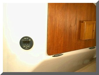
The Link 10 monitor was mounted as shown after
cutting a 2 inch diameter hole with the hole
saw.
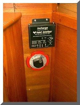
5. The Heart Interface In-Charge 3 stage alternator regulator was mounted immediately above the original "1-2-Both-Off" switch. This allows for short wiring runs to the alternator and a location where the LED indicators are fairly visible.
6. The "1-2-Both-Off" switch was removed and a teak panel will be installed to cover the existing hole. This panel will provide for the mounting of the three Blue Sea Mini ON/OFF Battery switches.
7. The wiring for the Link 10 was routed from the Link 10, down through the area of the engine instruments and from there out the bottom and across the 1" x 2" oak cross member under the galley counter top and down to the battery compartment. To facilitate running the wiring, I first pulled 2 messenger lines through this route using an electrician's snake.

Wiring that will attach to the Link 10 unit.
The
other ends will terminate as follows:
The twisted pair goes to the meter shunt.
The other three wires go to the house bank.
8. The wiring was connected to the back of the Link 10 meter assembly as per the instructions provided by Heart Interface. The other end of the wires will be connected to the meter shunt and the house battery later on.
Wiring attached to back of Link 10
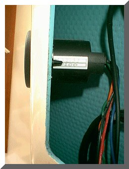
9. The Heart Interface Echo Charger was mounted to the aft bulkhead in the battery compartment and will be wired to the house bank and starter battery later on.

Echo Charger mounted in battery compartment.
10. A new panel was fabricated using 1/2 in. teak plywood and some teak trim. This will cover the hole where the "1-2-Both-Off" was originally installed next to the companionway steps and will provide a mounting platform for the new Blue Sea "On/Off" battery switches used for both banks and for the Emergency Parallel Switch. I have mounted 2 of the switches and the third one is on order. I also have the labels for the switches coming from Blue Sea.
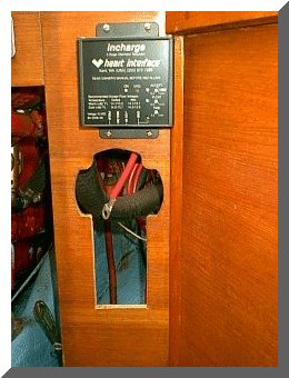

Photo of In-Charge alternator regulator and
battery switch panel temporarily installed.
Thursday February 21, 2002
1. Next came the task of removing the original alternator from the engine. The 12 mm nut on the mounting bolt that the alternator pivots on was frozen. Using a 3/8 in. drive ratchet with a 3/8 in. to 1/4 in. adapter and a 3 inch extension proved useless. All I managed to do was snap the 1/4 in. male portion of the 3/8 in. to 1/4 in. adapter. I made another trip to the hardware store (this is becoming the norm lately) and purchased a 12 mm 3/8 in. drive deep well socket. After another hour spraying with WD-40, tapping the nut with a drift punch and hammer and some 4 letter words of encouragement, I was able to remove the nut. :-)
2. Uh oh, that smile was a little premature. Seems the bolt is still frozen in the mounts. Unfortunately, there is very little room to swing a hammer behind the alternator. It was getting late in the day, so I saturated the ornery bolt with WD-40 and called it quits for today. (I have found that trying to handle a tough job this late in the day usually only gets me into deeper trouble.) I will go home, get some more tools and return tomorrow. Stay tuned for this saga.
Friday February 22, 2002
1. After yet another trip to West Marine to get the last battery switch, I returned to the boat to try some more "friendly persuasion" on the stubbornly frozen alternator bolt. After close to an hour of tapping on the bolt at the nut end (with the limited swing room for the hammer), I decided to take another approach. The bolt in question has a square but thin head which is at the front of the engine and rests against a ridge cast in the alternator foot so it will not twist. I attempted some more tapping with a center punch on the bolt head in hopes that it might free it up. No such luck. I finally decided to get out my set of carbide tipped drill bits to tackle the problem.
2. I center punched the center of the bolt head and then started with a 1/16 in. bit and drilled approximately 1/4 in. deep into the head. Then using successively larger bits, I continued drilling until I could simply pry the head off the bolt. Next I took out a trusty 1/4 in. diameter drift punch and tried to drive the bolt out from the front to the back. I gave up after about an hour and a half and soaked the entire area with WD-40. I will return tomorrow with some stronger penetrants and try again.

Frozen alternator mounting bolt after drilling
the head off. Care must be taken not
to use too
much force with the hammer and drift punch
so
as to not break any of the cast parts.
Click HERE for page 3 of DC Upgrade
Copyright 2001-2009 No duplication of any portion of this website without express permission.
Permission may be obtained by e-mailing the webmaster at
earlylight160@yahoo.com.