 |
|
|
Having hauled my fair share of 20 pound blocks
of ice over the past 19 years on my previous boat, I decided that one of
the upgrades high on my list of priorities for "Early Light" would be refrigeration.
Prior to selecting the type of refrigeration to install, I took into account
numerous factors. Among these were the following:
1. Amount of engine
run time I was willing to accept
2. How much time
do I intend to spend "on the hook"?
3. How much time
will be spent in a slip with AC shore power available?
4. What sources will
I have available to recharge batteries? i.e.: AC shore power charger, engine
alternator etc.
5. Climate of principle
use
6. Cubic feet of
box to be cooled
7. Amount of insulation
around box
8. Battery capacity
9. Do I need a large
freezer or mainly refrigeration?
10. Mounting space required
for compressor/condenser (how much storage space will I lose?)
11. Complexity of installation
12. Will refrigeration technician
be required to charge the system once it is installed?
After much thought and a lot of conversations over a cold beer with fellow sailors, I decided that an air cooled DC system with a large evaporator would best suit my needs. I then looked over a number of spec. sheets and talked to owners of various units to get a feel for reliability as well as asking about service after the sale offered by the manufacturer.
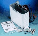
I ended up ordering the Adler Barbour CU-100
condenser unit and the VD-152 large vertical evaporator unit from JSI SailNet
in Florida. The evaporator unit provides for a small freezer compartment
and 3 vertical ice cube trays.
Supplies Required and Sources.
1. Adler Barbour CU-100
condenser unit ($530.00 from SailNet)
Tools
required.
1. 3/8 in. reversible
drill
The plan as anticipated.
After much thought and some consultation with
fellow Sabre 34 owners and the folks at Adler Barbour, I decided to install
the CU-100 condenser unit beneath the starboard settee. I will cut
out an opening in the settee face and install a louvered teak insert from
H & L Marine. The condenser unit will be positioned so that the
shroud of the condenser is up against this louver insert to allow for air
intake. This will provide a cooler location than the shelf in the
starboard sail locker (which is where Sabre installed similar units) since
it would be below the waterline and away from the engine. To get
rid of the heat in this space, I will run a flex duct up behind the settee
back so it exits in the forward section of the bookshelf. This will
be aided by an auxiliary 4 inch, 12 volt muffin fan purchased from Radio
Shack (rated at 85 cubic feet per min and draws a mere 0.32 Amps) which
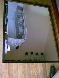
will run only when the compressor is running. The VD-152 large vertical
evaporator unit is to be installed on the forward wall of the icebox with
the top of the unit about 1 inch below the inner surface of the icebox
lid. The thermostat location would be on that same wall of the box
immediately adjacent to the evaporator and high on the wall as well.
A separate 15 Amp DC circuit breaker will be installed in a single breaker
panel (complete with a protective cover to prevent accidental switching
of the compressor/condenser) on the forward face of the galley just above
the access door for the icebox pump and to starboard of the small drawer.
Power will come directly from the main battery switch to the circuit breaker
and then from the breaker to a terminal block mounted near the condenser
unit. This cable run will be made using #6 AWG wire which will minimize
the voltage drop to approximately 1% (well below the 3% drop which is the
maximum that should be tolerated). Routing of the wiring as well
as the copper refrigeration lines and the thermostat cable will be discussed
below.
2. Adler Barbour
VD-152 evaporator unit ($302.41 from SailNet)
3. Blue Seas single
circuit breaker panel ($15.99 from West Marine)
4. Ancor 12 volt
15 Amp circuit breaker ($15.95 from West Marine)
5. 20 feet Ancor
#6 AWG red cable ($37.80 from SailNet)
6. 20 feet Ancor
#6 AWG black cable ($37.80 from SailNet)
7. Heavy duty crimp
lugs for #6 AWG wire (On hand)
8. Assortment of
cable ties (On hand from previous projects)
9. 11 inches of 1.5
in. X 1.5 in. hardwood (On hand from previous projects)
10. 14 inches of 3/4 in
X 1 in. hardwood (On hand from previous projects)
11. 1/2 in marine plywood
10.5 in X 11.5 in. (On hand from previous projects)
12. 80 and 110 grit sandpaper
(On hand from previous projects)
13. Epoxy resin and hardener
(On hand from previous projects)
14. 3 pcs. 8 in X
13 in. of fiberglass cloth (On hand from previous projects)
15. Acetone for cleanup
(On hand from previous projects)
16. Spray foam insulation
($4.00 from Ace Hardware)
17. Teak louvered panel
insert ($41.50 from H & L Marine)
18. 12 volt 3 inch muffin fan ($7.49 from Radio
Shack)
19. Stainless steel louver ($5.99 from West Marine)
20. Petit Bikini Blue EasyPoxy
paint (On hand)
21. Z-Spar Captains Varnish
(On hand)
22. Two 6 foot sections
of 1/2 inch foam pipe insulation ($4.98 from Ace Hardware)
23. One 3 foot section of 3 inch PVC pipe($5.90 from Ace Hardware)
24. One 90 degree 3 inch PVC elbow($2.19 from Ace Hardware)
Total cost of this project: $1012.00
2. 1.5 in. hole saw
3. 3 in. hole saw
4. 3 5/8 in. hole saw
5. Saber saw
6. Heavy duty crimp
tool
7. Box & open
end wrench set
8. 1/4 and 3/8 in
drive socket set
9. Screwdriver assortment
10. Small (2 in.) aluminum
fiberglass lay-up roller
11. 2 in. paint brush
13. 1 in. varnish brush
12. Small block plane
13. Crosscut saw
14. Rip saw
15. Finishing sander
16. Hacksaw
|
 |
Routing the tubing and thermostat cable.
1. Using a 1.5 inch hole saw, I drilled a hole in the FORWARD wall of the ice box as high as possible and all the way outboard (making sure to clear the aft set of teak guides for the countertop piece that covers the stove).
2. Next I removed the two plywood panels that form the bottom of the dry stores locker and selected a location for the next 1.5 inch hole as low as possible behind the stove allowing for clearance when the stove is swinging on the gimbals and clearance for the countertop piece to drop all the way down in the teak guides while using the stove.
3. I utilized the existing hole in the forward bulkhead under the dry stores locker to route the tubing and thermostat cable into the area occupied by the starboard water tank.
NOTE:
Be careful not to get your body stuck hanging
upside down in the dry stores locker.
Don't EVEN ask!!! :-)
4. I located and drilled the last 1.5 inch hole in the small bulkhead that divides the area beneath the starboard settee.
5. The tubing comes with insulation on the first two feet or so at the evaporator end. I carefully uncoiled the tubing (being careful not to kink it) and with the help of another person holding the evaporator I routed the tubing as previously described.
6. Once the tubing was routed, I covered
the remainder of the tubing with foam pipe insulation.
 |
 |
7. Next I ran the thermostat control
cable along the same route and spiraled it around the tubing to keep it
neat. I then clamped the tubing/thermostat cable at intervals to
prevent flexing and chafe.
Mounting the evaporator and thermostat unit.
1. After the tubing and thermostat cable had been run, I set the evaporator down (being careful not to crimp the tubing.
2. Next I taped the paper template supplied with the unit to the forward wall of the icebox and drilled the four 9/64 in. mounting holes for the four self taping screws.
3. Four one inch nylon spacers and four self tapping stainless screws were provided with the unit. I had to purchase two 1/2 inch long nylon spacers from the local Ace Hardware store and two longer (2 inch) self tapping screws for the upper two mounting holes. If you look at the top of the S-34 icebox, you will see that the wall has a 1/2 inch step in it, hence the longer spacers and screws.
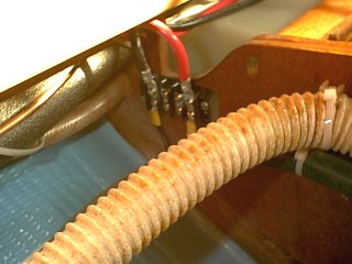
4. Once the evaporator unit was secured
to the wall of the box, I mounted the thermostat just inboard of it and
near the top of the icebox. The tubing from the thermostat is then
secured to the side of the evaporator between the metal and plastic plates
as per the instructions. This tubing may be seen where it attaches
to the black plates on the side of the evaporator unit in the below photograph.
 |
5. At this point, I filled the area where the tubing exits the box with a shot of spray foam, then once cured, I ground a little bit out so that it was recessed about 1/8 inch (just about to the back side of the fiberglass).
6. I now packed the area around the tubes
on both sides of the box with the "mortite" supplied by Adler Barbour.
 |
Routing the DC power cables.
1. I taped the DC hot and Ground cables together and started feeding them from inside the cabinet door where the icebox pump is located. I routed them under the icebox where the drain hose exits to go to the pump and pulled them through the area under the stove where the access door is, feeding them into the area below the dry stores locker.
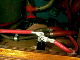
2. From there, they were routed through
an existing hole between the dry stores locker and the settee compartment
by the water tank. They were then run through a hole in the partition
in the settee to a heavy terminal block. The cables are #6 AWG, and
therefore require some heavy duty lugs and a special crimp tool.
I purchased this tool when rewiring my last boat, and it does a great job.
 |
 |
 |
3. Next I mounted the single circuit
breaker panel with protective cover in the teak face above the access door
to the icebox pump.
 |
 |
4. Returning to the area near the icebox pump, I routed the positive DC cable up the inside of the teak face to starboard of the access door and across to the circuit breaker (load side terminal). From the circuit breaker (line side terminal) I ran the positive lead over to the output side of the battery selector switch.
5. The ground cable was then run across
the teak face (beneath the access door) and up the 3/4 in. vertical strip
on the inboard side of the access door and across the inside of the facing
beneath the two drawers to the negative terminal of the batteries.
 |
Click HERE
for more of the refrigeration installation
Copyright 2001-2009 No duplication of any portion of this website without express permission.
Permission may be obtained by e-mailing the webmaster at
earlylight160@yahoo.com.