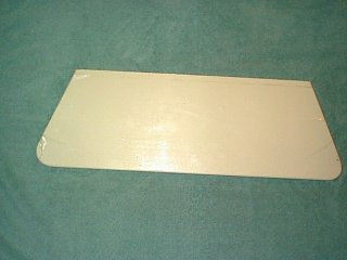
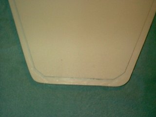
(Bottom view)
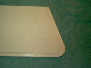
(Top View with protective film prior to routing forward edge)
|
Page 3 |
To fabricate the new hatch cover for the anchor locker, I first made a cardboard pattern of the existing hatch cover. The new cover will be a two piece affair splitting the hatch cover athwartships.
The after piece will be permanently mounted and only the forward piece will be hinged. I made the after piece to a fore and aft dimension of 8 inches. The underside was routed out so that when it sits on the recessed lip in the deck that the top surface is flush with the deck surface. This amounted to routing the underside edge to a depth of approx 3/32 inch with a width of 1/2 inch. The top surface of this piece will be routed on the top of the forward edge to 1/4 inch deep and 1/2 inch wide.

The original aftermost hinge was mounted to the after portion so as not to have holes in the deck to fill and two hinges were used for the forward portion of the lid (one in it's original location and a second one further aft). The original ring pull latch was let into the forward portion to a depth of 5/64 inch using a router and a 1 inch hole saw.

Next the after piece along with the composite filler and the backing plate were installed using stainless steel machine screws, large stainless steel fender washers and stainless steel nylock nuts.
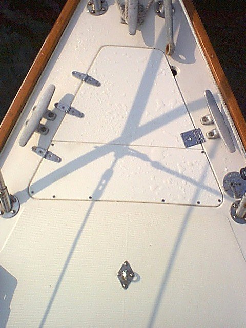
With the after piece now in place, the mounting template was placed on top of the new after piece and the original deck area immediately aft of it. This allows for the two aftermost windlass mounting bolts to be anchored through the original fiberglass deck and the two forwardmost bolts to be anchored through the new StarBoard material. The alignment to the anchor roller was double checked and the template taped in position for final drilling.
I marked the centers of the 4 bolt holes as well as the hole for the windlass drive shaft and the chain hole by using the template supplied with the windlass and a 3/64 inch drill. Once these hole centers were marked, the template was removed and the 4 holes for the mounting bolts were drilled using a 11/32 inch drill. Next I drilled the hole for the drive shaft using a 2-1/4 inch hole saw and the hole for the chain was drilled using a 3-1/16 inch hole saw. All areas of cored deck that were penetrated were sealed in the usual manner (remove core material, fill with thickened epoxy and re-drill). The windlass top unit was now bedded and mounted.

The next order of business was to mount the two foot switches. This required cutting two holes of 2 & 1/4 inch diameter using a hole saw. These holes were then treated the same as all others by sealing them with thickened epoxy. Each foot switch required drilling 6 holes for the self taping mounting screws. The switches were then bedded and secured to the deck.

The port and starboard mooring cleats were bedded and re-installed.
Prior to mounting the motor and gearbox, the entire inside of the anchor locker was given a fresh coat of gelcoat.

The motor and gearbox was then mounted to the underside with the help of a fellow Sabre sailor. (that damn motor/gearbox weighs approximately 30 pounds and trying to hold it in place while starting 4 nuts on the studs requires more than 2 hands but there was only room for two)
