Sections:
Theory |
Classification |
Types
Theory, Principles
A. Theory.
The average voltage is given by the following formula:
Eavg = 4FfTp x 10-8
 Where:
4Ff = the flux cut per second
Tp = the number of turns in the primary
Assuming that flux variations is sinusoidal, the form factor is equal to  p/2 = 1.11, thus the effective calue of the induced primary voltage:
Einduced = 4.44FfTp x 10-8
Ep = 4.44FfTp x 10-8
Es = 4.44FfTs x 10-8
This equations lead to:
Ep x Ts = Es x Tp
Ts should be divisible by four (4) so that the coils maybe effeciently group for series and/or parallel connections to balance and counteract magnetizing effect.
Similarly:
Ip x Tp = Is x Ts
Sections:
Theory |
Classification |
Types
Classifications
B. Classifications.
Transformers are usually classified through the following:
a) The number of phases: Three-phase or single-phase
b) Method of cooling
c) Terminal Voltage
d) Output, in KVA
e) Contruction
There are, however, two general classes of transformers:
1.  Power Transformers
These equipment transforms the voltage from generating stations to each end of the power transmission line. They are designed for maximum efficiency at full load. KVA ratings are usually larger than distribution transfromers, from 500 kVA at 67 kV.
2. 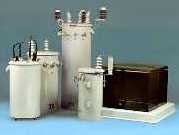 Distribution Transformers
Often found on transmission poles, and usually rated at 500 kVA or smaller for applciations 67 kV and below. These equipment are normally designed for 65°F temperature rise. Primary voltages: 12,470Y/7200, 13,200Y/7620, or 12,000D at 2,400 or 4,800 votls. Secondary voltage for single-phase could be 120/240, 240/480, 240/120, and for three-phase usually ar 208Y/120.
Sections:
Theory |
Classification |
Types
Types
There are, however, two general types of transformers:
1. Core-type
where the magnetic circuit takes the form of a single ring encircled by two or more groups of primary and secodnary distributed around the periphery of the ring. Usually these transformer offers high voltage with small output.
2. Shell-type
where the primary and secondary windings take the form of a common ring in which is encircled by two ir more rings of magnetic material distributed aroung the periphery. Usually these transformer offers low voltage with large output.
For Design Notes, click here.
Home |
EMD |
Sites |
ABdA |
Help |
E-mail