The AP5T-3.0 - A Very Different Beast New
Since October 1999, I've received emails
from 4 owners of the AP5T Rev 3.0 stating they have had problems
with reworking their mobo. The problem was they could not get the
core voltage lower than 2.5V, no matter how much resistance was
added to JP11. Then one of them, John Roberg-Larsen, took
the plunge and created an original 2.2V rework for the AP5T-3.0!
John has generously agreed to share his rework, so that other
AP5T-3.0 mobo owners can give it a try.
Calling all AP5T-3.0 Enhancers!
If you do try it or create your own rework or create a 2.4V
rework, E-Mail (hackedmobo@yahoo.com) what you did to me, and I'll put it on my homepage
here, including your name and email address. If you don't want
your email address published, let me know. Please try to be as
accurate and detailed as possible, preferably with some
descriptive diagrams.
Taming The Beast
- The 2.2V Rework
- The 2.2V Rework
#2 - Tamed Again!
- K6-2 450MHz
& 2.2V Rework #2
1. The 2.2V Rework
Contributed by : John Roberg-Larsen
Email : jrobergl@c2i.net
Date : January 23, 2000
Hi
Adrian
Yes, yes
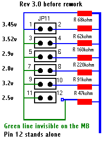
i have rework the parallel resistor circuit on JP 11 on rev
3.0 to 2.2 volt, sow i can use K6/2 - 400. Here is the
solution you have too soldering off the resistor who is att
the right side off pin 12 on JP 11. On rev 3.0 pin 12 stands
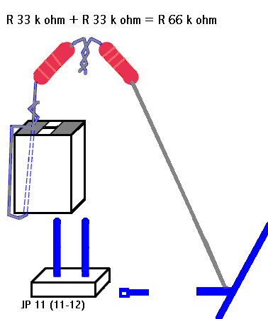
on it own with no connecting. The resistor is a 47 kohm. Then
you take 2 resistors off 33 kohm = 66 kohm and soldering one
leg off the resistor on to the long gate, and the oder end on
a jumper and put on pin 11. When you soldering off resistor
the volt drop´s from 2.5 v to ~1.75 v. Look att the gif
fil´s i nickt from you and reworkt hope it is ok.. The VR is
cold and the Pc work´s fine. All others pin on JP 11 drops ~
0.3 v but who care as long as i get 2.2 v. on pin 11-12. And
i measure the I/O volt and ok 3.3v. I try Sandra benchmark
and i get with bios 1.80 988 mips, 230 mflops, with bios 1.82
i get 1032 mips, 230 mflops. I disabled the System bios
casheable, but i can´t turn on the write allocation with
setk6 /on. What is wrong? I use win 98 with 128 mb edo ram.
And with WCPUID it dos not report any external and clock
ratio on Clock Frequency. Do you use SDRAM??
1. AP5T
- 3
2. Bios R.1.82
3. AMD K6/2 - 400
4. 66 mhz x2
5. Vcore = 2.2 volt
AP5T -
Rev 3 have a parallel resistor circuit, so you cannot adding
resistors to lower the voltage, it stay on 2.5 volt on pin 11
- 12 on JP11
:-) John
jrobergl@c2i.net
Norway
2. The 2.2V Rework #2 - Tamed Again!
Contributed by : Pär Andersson
Email : dt98paan@forsmark.uu.se
Date : February 29, 2000
Hi
Adrian
Thanks for a nice and helpfull page. Without it I would most
likely still be using my old 200MHz... ;)
This is hopefully all you wan't to know about how I enhanced
my AP5T, for your "How You" page. I am from Sweden
so please escuse my spelling/grammar.
General
info:
Before:
BIOS: 1.82
CPU: AMD K6 200MHz
Bus and multiplier: 66MHz*3
Core V: 2.9V
After:
BIOS: 1.82
CPU: AMD K6-2 450Mhz
Bus and multiplier: 75MHz*6(2)
Core V: 2.2V
Study:
I found
your page while searching the net for info about running a
K6-2 on my AP5T, so your page was exactly what I where
looking for. After reading you page I checked my revision and
found out that I have a AP5T 3.0, "The Beast". So I
read johns results on the 3.0 page.
The
rework:
I got to
work by removing all cards, ram and the cpu. I put the
resistors in the socket to measure the core voltage.
JP11(11-12) gave me 2.5V as expected :(
So my
next step was to check the MoBo with a multimeter to see if
Johns results where correct. They appeared to be 100%
correct. To increase the resistance I apparently had to
remove the annoying 47kohm resistor (next to pin 11-12 on
JP11) that was in parallel to the others and therefore
prevented me to increase the resistance. This however didn't
scare me. I got it of quite easy with a solderer(?) and a
screwdriver.
With it
removed I got 1.25V to the CPU, this is too low, so I had to
add resistance. Insted of adding resistors like john did I
found it a lot more easy to use the resistors already in
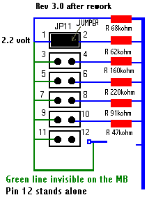
place. I first tried to jumper p1-2 on JP11, according to
johns image that would give me 68kohm which is very close to
the 66kohm he used. I really hit the jackpot, because this
gave me EXACTLY 2.20V to the cpu :)
Before
plugging the K6-2 in I tried some other JP11 settings out of
curiosity. I wanted to be able to get back to 2.9V in case I
ever would need to plug my old K6 in again. Some of these
results are in the table below. I have also attatched
modified version of johns images showing my AP5T 3.0
modification to this mail, I hope he doesnt mind that I use
his images.
Test
results:
| JP11 |
Core Voltage WITH
47kohm resistor REMOVED from the Motherboard! |
|
| One jumper: |
|
|
| 1-2 |
2.2V |
I use this for my K6-2
450 |
| 3-4 |
2.28V |
|
| 5-6, 7-8, 9-10, 11-12 |
between 1.25 and 2.0V |
useless for any current
CPU |
| Two jumpers: |
|
|
| 3-4 AND 9-10 |
2.98V |
|
| 1-2 AND 9-10 |
2.90V |
perfect for my old K6 200 |
How
to find core voltages:
By
calculating the total resistance it is quite easy to find
jumper settings for diffrent core voltages.
To calculate the total resistance you use R=1/((1/R1)+(1/R2))
The
original 2.9V setting (5-6) had
R=1/((1/160)+(1/47))=36.3kohmi (look at johns images).
By testing a few combos on my calculator I found that (1-2
and 9-10) would give R=1/((1/68)+(1/91))=38.91kohm. This was
close enough and gave 2.9V
How to
find 2.4V for K6-III:
My 2.2V
setting has 68kohm.
And the 2.5V setting apparently use only the 47kohm resistor.
So you should calculate diffrent jumper settings to try to
find a value that is something beween this values. A quick
guess is that 5-6 AND 9-10 (58kohm) would give approx 2.4,
but I didn't test it and I am not going to take my computer
to pieces again to do it. If you cant find a resistance that
gives the correct voltage you can start adding resisted
jumpers like the ones Adrian used on the 3.1 rework.
Would it
work?:
After
this I inserted the new shining K6-2 450 with CPU fan,
changed the multipel to 2, put in the graphics card +
keyboard and booted the machine. I was a little worried, but
it worked! So I put all my other disks and stuff in and it
still works perfectly. The BIOS even turns Write Allocation
on.
Stability:
It has
been running perfectly a whole week now. I always keep my
computer on 24h/day. Most of the time in Linux but also in
windoze. Both the CPU and the VR is really cool, so I got a
much faster system for a really cheap price.
Benchmarks:
SiSoft
Sandra results:
Before:
CPU: 612 MIPS, FPU: 232 MFLOPS
CPU: Integer MMX: 347, Float-Point FPU: 126 it/s
CPU/Mem: 66 MB/s, FPU/Mem: 65 MB/s
After:
CPU: 1172 MIPS, FPU: 536 MFLOPS
CPU: Integer MMX: 1194, Float-Point 3DNow!: 895
CPU/Mem: 81 MB/s, FPU/Mem: 85 MB/s
WinBench
99 results:
Before:
CPUmark 99: 15.9
FPU WinMark: 650
After:
CPUmark 99: 22.1
FPU WinMark: 1460
After
(with WC on):
CPUmark 99: 22.3
FPU WinMark: 1480
Regards
//Pär
Andersson <dt98paan@forsmark.uu.se>
3. K6-2 450MHz & 2.2V
Rework #2
Contributed by : Mathew
Email : Mat_Cottrell@hotmail.com
Date : April 27, 2000
Dear
Adrian
Firstly
I'd like to thank all you boys for the information that has
enabled me to hack my motherboard. You should all be working
for NASA as far as I'm concerned.
I have a
rev 3.0 (The beast) motherboard but I started off by
following the Adrian's HOW? instructions. I put the three 100
ohm resistors in place and found that I was unable to drop
the V Core voltage lower than 2.5V. I then reconsulted your
web page and was overjoyed when I read the contributions from
John and Par. Off I went to purchase my K62-450 confident
that the hack would work.
I then
followed the instructions contributed by Par to the letter
and have had the exact same good results.
Removing
the 47K resistor was easy, although I have spent many happy
hours with my soldering iron and fear a less expirenced
solderer may be put off by performing the hack. I inserted
the prong of my multimeter under the resistor and then when I
heated up one end of the resistor it fell off. I then spent
10 minutes looking for the resistor fearing that it was
wedged between a component and would cause a short when
applying power to the mother board, which was still in the
chassis as I was too lazy to take out.
With the
resistor gone I powered up and measured 1.25 volts across the
100 ohm resistor(Adrian's HOW? note, then
Jumper on JP11 1-2 = 2.2V
Jumpers on JP11 1-2 and 9-10 = 2.9V
So I removed the three 100 ohm resistors, put the K62-450,
ram and video card in.
Set jumpers to 66 bus speed X 5.5 = 363MHz as I was worried
cos I hadn't applied the win95 AMD patch.
The bios reported that a 486DX2 66HMX was installed and
defaulting the bios did not change this, BIOS version 1.4.
Able to boot into Win95 no problems
Flashed bios to V1.82 and applied win95 AMD.
Set jumpers to 75 bus speed X 5.5 = 412MHz. put all cards
back in system, everything OK and system stable.
CPU cool.
SetK6 reports write allocation enabled.
I shall try shortly to jack system up to 450MHz which I'm
sure I will have no trouble doing.
Thank
you all again
Brgds
Mathew
Disclaimer
Adrian
Last revised: October 29, 2000.