Home
Beginning Modeling
Advanced Modeling in hamaPatch
Inspired by Miyoken's tutorial modeling a guitar.
This tutorial was written assuming you have general knowledge of hamaPatch or have at least browsed the hamaPatch Help and have experience using topics covered in the Beginning Tutorial(specifically knowledge of extrusion and connecting points).
You can Download a zip file containing models from various stages of the tutorial. These models will be referred to at the end of the section to which they relate.
Grid size assumed to be .5. Adjust Grid Setting by clicking Show on the View window and choosing Grid Setting and typing .5 in the Size field.
Body
Open hamaPatch and a new patch_obj is created. Rename this patch_obj to guitar_body using the ... button under Object on the Dialog Window. Change the color to a light brown-orange in the same window area by clicking the colored box beside the patch name.
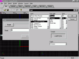 Click Model on the menu and choose the Text option. A pop-up window should appear prompting you for the text and allowing you to choose a font. Click the Font button and choose Times New Roman with a size of 10 and leave it as Regular. Click OK and the Font name appears in the previous window. Now type the text. The closest character shape to the body of a guitar is the set of curly braces {}. Type these in the Text field and click OK. This will generate two splines in the shape of the curly braces, but it will not make them solid faces.
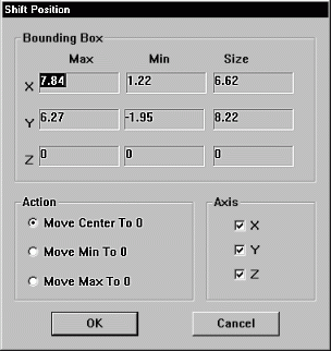 Expand the Front view (XY view or window C in my setup) and notice that the braces are offset to the right of the origin. However, we want them to be centered at the origin. So Select all points either by clicking the Select heading on the menu and choosing All or by using the
  Square Select tool. Now choose Model - Shift Position from the menu. A new pop-up window appears.
Ignore the Bounding Box section. Make sure all 3 axes are turned on and the Move Center to 0 option is chosen then click OK. The two splines should now be positioned on either side of the Y-axis.
 Deselect all points via the menu (default shortcut key is Enter) and Square Select at least one point on the right brace. Select - Connected (default shortcut C) and press the Delete key or choose Edit - Cut. If we had not used two braces, the single brace would have been centered exactly at the origin not at some offset. We could have calculated an offset and redefined the Bounding Box or used the Translation option, but to me this seems quicker.
Use the Camera toolbar's tools to
  Zoom in on and
  Pan down to the lower most corner of the brace and Square Select the bottom most of the two points. Use the Select - Curve option on the menu or the Patch tool
  until the line from the bottom point to the point directly above is selected and use the
  Delete Select Curve tool. Pan up and use the
  Hand Select Curve tool from the Patch toolbar to select the same curve on the uppermost set of points and use the
  Delete Select Curve tool again. All three methods do the same thing, use whichever method you prefer from now on. Select - All points and use the
  Round tool from the Patch toolbar to make everything curvy once again.
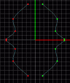 There should now be two unconnected sets of points. Choose a point on the inner most set (closest to Y-axis) and Select - Connected, then delete those points. Select - All of the left over points and click the
  Clone tool from the Patch toolbar (this will make an exact copy of the selection directly on top of the selection, but only one set is currently selected). Choose Model - Flip X from the menu and you should see two mirrored sets of points on either side of the Y-axis. Save current progress. guitut01.hmp
Use the  Add Point tool from the Patch toolbar to connect the top left most point and the top right most point. Remember to click somewhere away from the other points of your model and drag/weld each point of the new spline individualy into the desired position. Pan down and repeat this for the two bottom most points.
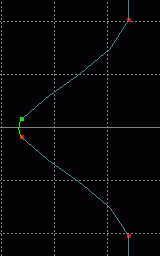 Pan over to the two left most points. These two points need to be one point. There are several ways to do this, but one of the most precise ways is to calculate the mid point of the points and delete the two points. To do this select either point and then select the curve connecting these two points (by one of the three methods mentioned above). Choose Model - Subdivide Select Curve from the menu and type 2 in the entry field and click OK. This feature lets you determine how many times you want to subdivide the curve currently selected. In other words, it asks how many equally long curves (lines between points) you want the selected line to become. One at a time, select each point on either side of the new point and use the
  Delete Point tool from the Patch menu to delete each point. Pan over and repeat the process on the mirrored side. Select - All points and click the
  Round tool once more. In hindsight, this operation could have been performed before the cloning and mirroring in order to save even more time.
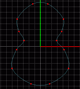 Zoom out
  and select the two new points using the
  Square Select tool and turn off the Y and Z axes
  . Choose the
  Scale tool and click and drag the mouse so that the points come nearer the center of the object (not too far, roughly 1 grid space in from either point above the selection, remember we are making a guitar). The top is supposed to be slightly smaller than the bottom. Square Select the top 6 points, making sure to include the 2 currently selected points in the selection square. This will unselect what was selected and select what was unselected (provided you have not changed the Select Vertex option from Inverse under the etc. tab on the Dialog Window). Scale the top points and rescale the middle points if needed, until it looks fairly good to you. Mine is a bit too tall so I turned on the Y-axis and turned off the X-axis and scaled all points slightly. By now you should have a recognizable guitar shape.
Change the view to Right, Select - All points and  Extrude 1 and 1/2 grid squares along the Z-axis. You should now have a partialy solid object. Save current progress. guitut02.hmp
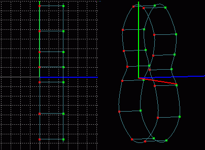
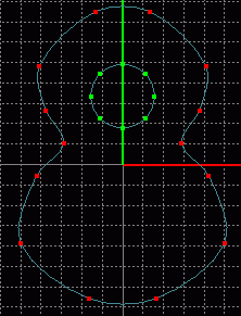 Now we need to make a circular hole in the body of the guitar. Change back to a Front view and choose Model - Insert - Circle(8) from the menu. This will place a predefined circle containing 8 points onto the XY plane which should line up with the front of the guitar. Turn on all axes and Scale the circle slightly then position it using the Manipulator
  along the X and Y axes until it looks correct. My circle is about 3 grid spaces in diameter. The circle should be placed roughly 3 diameters (3 lengths equaling the hole's diameter) from the bottom and one from the top.
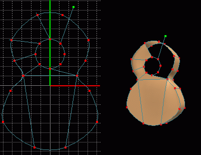 Verticaly expand a Front window and some Perspective window (window B in my setup) so that there is one view on either side of the screen. In both views turn on Show - Point and Curve and turn on Show - Surface (only in perspective view) under the Show heading on the View Window. Rotate and Zoom in on the Perspective view slightly. Add Points using the
  Add Point tool (Still remembering to create points away from the model and drag back). Create points and weld them to the circle in the Front view, and then weld them to a near outer point in the Perspective view by right clicking when the points overlap. Make sure each surface contains exactly four points or else your patches may wrinkle. This is how holes are made in patch modeling. You must think ahead a few steps and build the model around the hole, creating an absence of faces (splines more than 4 points) wherever holes are desired.
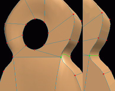 You may notice some of the patches are lumpy around the edges, this is because they have not been peaked. You must choose the curves you wish to peak individualy using the
  Translate tool the
  Select Curve tool and the
  Peak tool. You need to select each end of the curves extending from the circle and peak along that curve in either direction. If you just click the point and then peak, all extending curves will be peaked and the guitar's necessary curves will be lost. However, you can also use the
  Hand Select Curve tool from the Patch toolbar to select any curve making up the circle and choose Model - Peak (Around Select Curve) function. This function will act on each point along the spline to which the curve you selected belongs. At every point on the spline, any curves passing through that point that do not belong to the selected spline will be peaked. This function allows you to quickly peak (and thereby flatten) many curves in an object, but can preserve the main circular/curved shape of the guiding spline. Repeat the process by selecting one of the original curves of the curly braces making up the guitar body and choosing Model - Peak (Around Select Curve).
Staying in a Perspective view, Select - All points and choose Model - Flip Z from the menu. The guitar should invert now and you can connect the back to form faces in the same manner as before. Remember to make each patch out of four points. You once again need to flatten the back via one of the methods mentioned above. Afterwards, select all points and Model - Flip Z again to reorient the guitar.
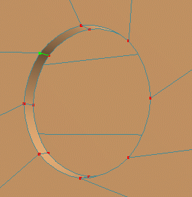 Now we need to make it look slightly more believable. Still in a Perspective view, Square Select a single point on the center circle and choose a curve that follows around the circle (or use Hand Select Curve tool). Choose Select - Spline from the menu and all points of the circle should be selected. Click the
  Extrude tool and use the
  Manipulator to move the extruded portion somewhat (about 1/3 a grid space) along the Z-axis. You will need to
  select a curve on the original circle and use Model - Peak (Around Select Curve) so that the small lip does not appear puckered. This will serve to make it look like the guitar is made from some thicker material and not paper (as it appeared to be before). Save current progress. guitut03.hmp
Tutorial created by Jonathan Lee Dec. 31, 2001. Updated Jul. 13, 2002 for version 2.8.1.
Submit question, comments, or ask for further instruction from draven2561@hotmail.com
Part 2
Home

 Click Model on the menu and choose the Text option. A pop-up window should appear prompting you for the text and allowing you to choose a font. Click the Font button and choose Times New Roman with a size of 10 and leave it as Regular. Click OK and the Font name appears in the previous window. Now type the text. The closest character shape to the body of a guitar is the set of curly braces {}. Type these in the Text field and click OK. This will generate two splines in the shape of the curly braces, but it will not make them solid faces.
 Expand the Front view (XY view or window C in my setup) and notice that the braces are offset to the right of the origin. However, we want them to be centered at the origin. So Select all points either by clicking the Select heading on the menu and choosing All or by using the
  Square Select tool. Now choose Model - Shift Position from the menu. A new pop-up window appears.
Ignore the Bounding Box section. Make sure all 3 axes are turned on and the Move Center to 0 option is chosen then click OK. The two splines should now be positioned on either side of the Y-axis.
 Deselect all points via the menu (default shortcut key is Enter) and Square Select at least one point on the right brace. Select - Connected (default shortcut C) and press the Delete key or choose Edit - Cut. If we had not used two braces, the single brace would have been centered exactly at the origin not at some offset. We could have calculated an offset and redefined the Bounding Box or used the Translation option, but to me this seems quicker.
Use the Camera toolbar's tools to
  Zoom in on and
  Pan down to the lower most corner of the brace and Square Select the bottom most of the two points. Use the Select - Curve option on the menu or the Patch tool
  until the line from the bottom point to the point directly above is selected and use the
  Delete Select Curve tool. Pan up and use the
  Hand Select Curve tool from the Patch toolbar to select the same curve on the uppermost set of points and use the
  Delete Select Curve tool again. All three methods do the same thing, use whichever method you prefer from now on. Select - All points and use the
  Round tool from the Patch toolbar to make everything curvy once again.
 There should now be two unconnected sets of points. Choose a point on the inner most set (closest to Y-axis) and Select - Connected, then delete those points. Select - All of the left over points and click the
  Clone tool from the Patch toolbar (this will make an exact copy of the selection directly on top of the selection, but only one set is currently selected). Choose Model - Flip X from the menu and you should see two mirrored sets of points on either side of the Y-axis. Save current progress. guitut01.hmp
 Add Point tool from the Patch toolbar to connect the top left most point and the top right most point. Remember to click somewhere away from the other points of your model and drag/weld each point of the new spline individualy into the desired position. Pan down and repeat this for the two bottom most points.
 Pan over to the two left most points. These two points need to be one point. There are several ways to do this, but one of the most precise ways is to calculate the mid point of the points and delete the two points. To do this select either point and then select the curve connecting these two points (by one of the three methods mentioned above). Choose Model - Subdivide Select Curve from the menu and type 2 in the entry field and click OK. This feature lets you determine how many times you want to subdivide the curve currently selected. In other words, it asks how many equally long curves (lines between points) you want the selected line to become. One at a time, select each point on either side of the new point and use the
  Delete Point tool from the Patch menu to delete each point. Pan over and repeat the process on the mirrored side. Select - All points and click the
  Round tool once more. In hindsight, this operation could have been performed before the cloning and mirroring in order to save even more time.
 Zoom out
  and select the two new points using the
  Square Select tool and turn off the Y and Z axes
  . Choose the
  Scale tool and click and drag the mouse so that the points come nearer the center of the object (not too far, roughly 1 grid space in from either point above the selection, remember we are making a guitar). The top is supposed to be slightly smaller than the bottom. Square Select the top 6 points, making sure to include the 2 currently selected points in the selection square. This will unselect what was selected and select what was unselected (provided you have not changed the Select Vertex option from Inverse under the etc. tab on the Dialog Window). Scale the top points and rescale the middle points if needed, until it looks fairly good to you. Mine is a bit too tall so I turned on the Y-axis and turned off the X-axis and scaled all points slightly. By now you should have a recognizable guitar shape.
 Extrude 1 and 1/2 grid squares along the Z-axis. You should now have a partialy solid object. Save current progress. guitut02.hmp

 Now we need to make a circular hole in the body of the guitar. Change back to a Front view and choose Model - Insert - Circle(8) from the menu. This will place a predefined circle containing 8 points onto the XY plane which should line up with the front of the guitar. Turn on all axes and Scale the circle slightly then position it using the Manipulator
  along the X and Y axes until it looks correct. My circle is about 3 grid spaces in diameter. The circle should be placed roughly 3 diameters (3 lengths equaling the hole's diameter) from the bottom and one from the top.
 Verticaly expand a Front window and some Perspective window (window B in my setup) so that there is one view on either side of the screen. In both views turn on Show - Point and Curve and turn on Show - Surface (only in perspective view) under the Show heading on the View Window. Rotate and Zoom in on the Perspective view slightly. Add Points using the
  Add Point tool (Still remembering to create points away from the model and drag back). Create points and weld them to the circle in the Front view, and then weld them to a near outer point in the Perspective view by right clicking when the points overlap. Make sure each surface contains exactly four points or else your patches may wrinkle. This is how holes are made in patch modeling. You must think ahead a few steps and build the model around the hole, creating an absence of faces (splines more than 4 points) wherever holes are desired.
 You may notice some of the patches are lumpy around the edges, this is because they have not been peaked. You must choose the curves you wish to peak individualy using the
  Translate tool the
  Select Curve tool and the
  Peak tool. You need to select each end of the curves extending from the circle and peak along that curve in either direction. If you just click the point and then peak, all extending curves will be peaked and the guitar's necessary curves will be lost. However, you can also use the
  Hand Select Curve tool from the Patch toolbar to select any curve making up the circle and choose Model - Peak (Around Select Curve) function. This function will act on each point along the spline to which the curve you selected belongs. At every point on the spline, any curves passing through that point that do not belong to the selected spline will be peaked. This function allows you to quickly peak (and thereby flatten) many curves in an object, but can preserve the main circular/curved shape of the guiding spline. Repeat the process by selecting one of the original curves of the curly braces making up the guitar body and choosing Model - Peak (Around Select Curve).
 Now we need to make it look slightly more believable. Still in a Perspective view, Square Select a single point on the center circle and choose a curve that follows around the circle (or use Hand Select Curve tool). Choose Select - Spline from the menu and all points of the circle should be selected. Click the
  Extrude tool and use the
  Manipulator to move the extruded portion somewhat (about 1/3 a grid space) along the Z-axis. You will need to
  select a curve on the original circle and use Model - Peak (Around Select Curve) so that the small lip does not appear puckered. This will serve to make it look like the guitar is made from some thicker material and not paper (as it appeared to be before). Save current progress. guitut03.hmp