Mar 1
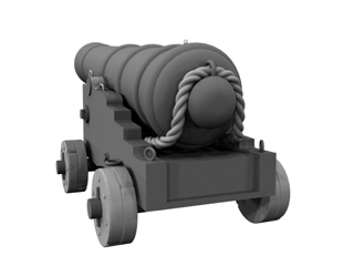
I think I can say the 24 pounder is finished. I've tryed placing some of them on deck; they look great but, as was expected, the number of polygons that each of them has makes the system rather slow, so I'll keep them hidden as I go on modelling.

Feb 27
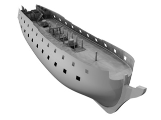
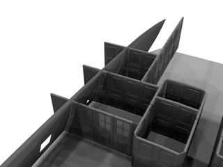
At last I've managed to fix the aft screens. I have also detached the doors as independent objects, so as to be able to rotate them around their hinges. With the lower deck gunports already cut off, the overall view of the model has a somewhat more impressive look.
As far as the gun is concerned, I've added the running rigging for recoil and replacement of the piece. For this thiner lines I've used simple rendereable paths, so as not to increase the number of polygons too much. Adding a proper rope texture later on will make them look just fine.
Today I have double polygon count: 134,045 for the ship; and 66,048 for the gun.
Feb 25
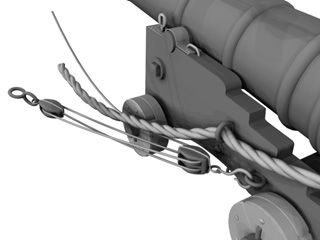
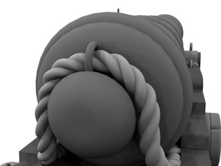
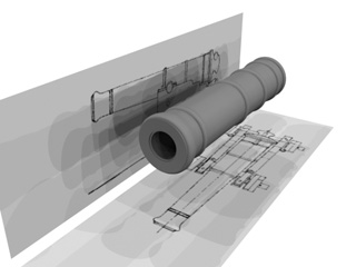
I've made an interesting mistake that I belive would be worth adressing. I've modelled almost the whole gun working just on one side of the structure, so as to make a mirror copy of it later on, obtaining the full object, it being perfectly simetrical. Initially I used the same technique when adding the bold rope that goes through the back ring of the gun... but, as you can see in the picture, in this case the trick does not word at all, because when the rope is mirrored the new half has its twist effect inversed, thus ruining the effect of a continous line that would be desireable. In the second picture the problem has been solved.
Feb 24
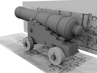
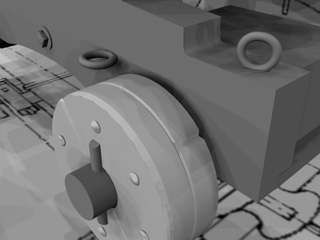
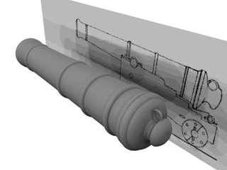
A general view of the gun progress, and some detail on the items added to the carriage. I have added a little bit of "melt" effect to the rings and screws so as to make the look more realistic than they would if they were perfectly geometric.
Feb 23
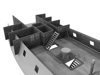
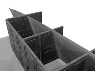
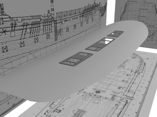
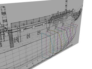
I'm having quite a lot of trouble adjusting the screens that make up the distribution of cabins on this deck. Here it can be seen that I have managed to give them the appropiate curved shape to fit on the deck; and the adjustments of the insets of the outer screens so that they look right against the side.
Feb 20
The centre part of the deck, almost done. I've also cut up the gunports; judging the distance in-between them I don't think there will be much deck space to spare when the guns are placed. A detail of the axis of the gun; I think it would be a good idea to keep the gun itself as a sepparate object from the carriage, with the pivot point centered on the axis, so that I can trim the elevation later on realistically.

Feb 19
The cannon, a little bit more advanced. I'll try to keep the taper effect (that produces the diameter variation) uncollapsed, so that I can adjust it easily later on to obtain guns of different wheight. Here you can see some more detail that I've been adding to the deck (the shot garlands, and the lines around the hatchways). The ropes are rendereable paths, to which I've given a very slight curve to make it look like the natural slack of an almost taut line.
Feb 17
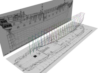
This is an approximation of the distribution of cabins on this deck. On the other hand, I've started with the modelling of a 24 pounder, so as to have something different to work with to ease my mind. The barrel is a hollow cylinder, to which I have increased the polygon detail on the mouth to be able to apply the rounded shape. The rings are simple torus objects.
Feb 16
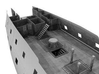
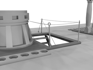
Default lighting is not good any more for previewing the scene in detail, so I have made a simple light dome (about 24 lights) with low intensity, to get a smooth shadow effect on the objects. Improvement is quite obvious.
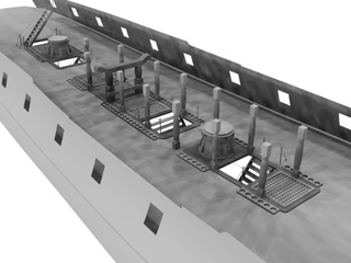
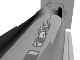
I've modelled the capstan as well as the hatchway stairs. You might notice that the capstan's base is not parallel to the deck: that's because I'm not sure as to whether I sould leave it squared with the worlds axis (that's how it is now), or with the deck's inclination. Anyhow, I can leave it as a correction to do later on.

Feb 13
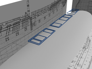
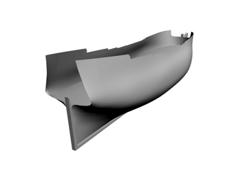
First unbeliveable mistake (it was about time): for some odd reason I've misplaced the upper deck in the place where the lower deck should be (?), so I've had to undergo quite a lot of knotting and splicing with the model. On top of that I've realised that the hull object is too irregular to get the boolean operations right for the decks, so I've had to make a copy of the hull and compleately seal it to get a closed object as a reference for the shape of the decks. You can see here the resulting closed hull, as well as the booleaned decks with all problems fixed.
It's Friday, time for polygon count: 53486, quite an important progress.
Feb 11
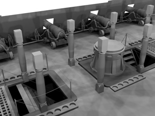
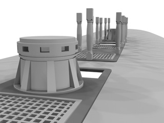
The best reference for placing the multiple objects on deck would be the hatchways that lead to the other decks. I've prepared a shape with the gratings layout for this deck, adding the holes and the columns.
Feb 9
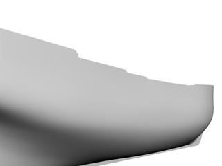
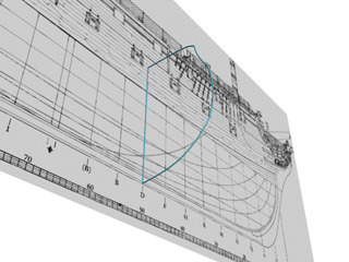
I've extended the side curve to get as far up as the reel on the whole length of the ship. I've cut the shape of the reel with a boolean operation with the help of a path drawn with the side blueprint.
Feb 7
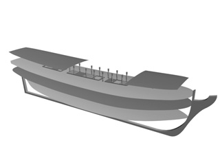
This is the plane for the upper deck. There should be a couple more on top of it, but I have chosen it as the starting point because it's the uppermost that runs continuouslly fore and aft. Even though it might not look so, it is quite obvious that a ship's deck is not flat: it is curved fore and aft (the stem and the stern are higher that the middle), and transverselly (both reels are higher than the centre). I've tried to get the curve as close as possible to the blueprints.

Feb 6
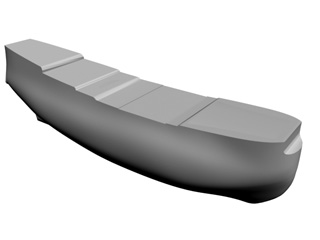
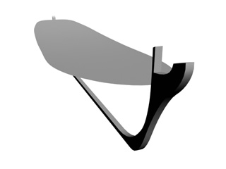
After applying the surface, both stem and stern need quite a lot of retouching, so I have added the keel as a reference for the shape. This object is just a shape slightly extruded. It really should be made of several different shapes grouped together, but I will keep it simple for the time being. I will detach them later on, when I get into some more detail.
I've happily gotten to the first weekend of the project. I'll take the chance to do a polygon count: 8738.

Feb 5
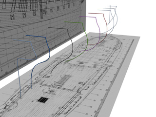
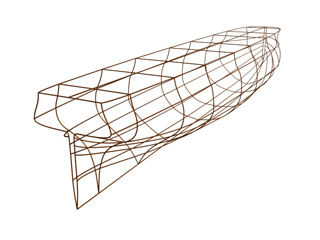
Using all the bulkheads the resulting model is quite precise, but I've found it quite difficult to retouch after applying the outward surface. I have therefore proceded to reduce the number of paths used, leaving only those that best define the shape of the hull. In the picture you can see the appearance of the paths with the cross-seccion applied, and mirrored in order to get the other half of the hull.
Feb 3
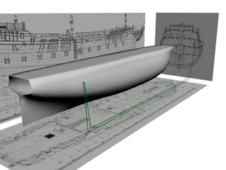
I think that the best strategy for modelling the hull would be to begin with the bulkheads (modelled as paths), and get them joined together with a cross-section modifier. For the time being I will use as the main reference the only straight line that the hull has (the keel), as well a dummy plane where the main deck will be (I'll have the chance to delete it and replace it with the real curved deck later on).
Feb 2 2004
As I'm not quite sure about what level of detail I would get up to with the model, I belive it would be best to begin with the overall structure and increase the detail as I make progress. Therefore I will begin with the hull basic form; to make that I've pasted the blueprints for the side, top and front view into some planes, to put them in the scene as a general reference.