|
When you try to use a standard carbon tube as a spar
you find that the main design constraint is the
section thickness where the tube terminates, near the
wing tip. At this point, the end of the tube should
lie at the position of maximum thickness for the
section.
|
| |
|
For a 0.5" ID commercial tube the OD is 0.56".
Foam-cutting considerations dictate an additional 0.1"
for the section thickness, including 0.02 of skin
thickness. That means 0.66" thick at the outer end of
the tube.
|
| |
|
For an HN345sr the thickness is 8.05% so the chord at
the outer end of the tube needs to be .66/.0805 =
8.2". I'm calling this the reference chord.
|
| |
|
I chose the HN345sr because it is used on the
NYX and because it's new and sexy. Whatever section
you choose, you need to work out this chord first. You
will need a tool like Compufoil to provide thickness
data. Remember that there is no warning if the tube thickness
exceeds the airfoil thickness at any point. Just be careful.
|
| |
|
Another minor constraint is that you do not want more
than 22" of the tip to be unsupported (tubeless).
This judgement depends on the layup you intend to use.
I intend to use Carbon Uni.
|
| |
|
The end of the tube is a stress-riser and should be
situated away from a panel break, another potential
stress-riser.
|
| |
|
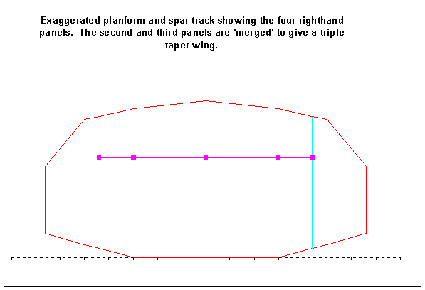
The solution creates a triple-taper wing with an
automatically straightened trailing edge (for any
sweep) and a straight tube path. All four Liftroll
panels are used but one of the breaks is used for the
reference chord and is automatically "hidden" by
extrapolating the subsequent chord. So you can only
see three panels in the finished product. The tube
terminates in the middle of the second actual panel.
|
| |
|
One other feature of the solution is that the forward
sweep is chosen to place the spar tube over the
anticipated CG. It may then be used for ballast. You
might want to use an analytical technique to predict
the CG. I just guessed.
|
| |
|
The positions of the tube holes as offsets from the trailing edge of the templates is also calculated.
For the HN345sr at the reference chord of 8.2" it is 5.609" from the rear at the point of maximum thickness.
This is a data entry item.
|
| |
|
A major warning: The tube path is straight when looked at from above (plan view). It also has to be straight
in frontal view. You may not get away with overlooking this fact.
|
| |
|
If you're interested, the Excel file is downloadable
from right here.
|
|
|
I am going to get all this cut by Laszlo Horvath at:
compufoamcore.com
|
|
Here are some notes relating to cutting
|
|

A 3-Piece wing
|
|
|
This design is for a 3-piece wing like a Mantis. There are two tips and a center section in a 3-piece wing. The center section is flat and is made out of the two inner panels from your specification. The three outer panels go to make each tip. The trailing edge of the tips is swept forward a little but is kept straight so that the layup is easy.
|
|
The Spar Tube Tunnel
|
|
|
The spar is a carbon tube with an outside diameter of 0.56". It needs a tunnel of diameter 0.57" - 0.58" to be cut in the foam so that it is easy to get in and out and so that there is a little bit of room for glue.
|
|
|
The tunnel needs to be straight when looked at from above and when looked at from the front or back. The center section of this 3-piece wing will be made by joining the two innermost panels together. The tunnel needs to be cut so that it is always the same distance away from the bottom of the foam blank. If you cut it so that it it is the same distance from the top and bottom surface of the wing, and you haven't thought it all out carefully in advance, then you will be making a small but important mistake.
|
|
|
The tunnel should be in the middle of the foam at the 9.3" chord. Let's imagine that its center is 1" above the bottom of the foam blank at this point. The center also needs to be 1" above the bottom of the foam blank at the 10" chord. This should place the tunnel slightly nearer the bottom than the top of the wing section at the 10" chord. If you overlook this subtlety then the tube will have to bend when you bag everything up. Bad news. Warp inevitable.
|
|
|
One way you could check that you've got it right is to set the two inner sections together, in their shucks, on a flat surface and try to slide a .56" tube or dowel through. It should be fairly easy but not sloppy and everthing should stay flat. Do this test _before_ the layup!
|
|
|
The tunnel needs to be the same distance from the top and bottom surfaces of the wing in the second panel. At the end of this panel there is only about 0.05" of foam above or below the tunnel. If you can't cut this close for any reason then redesign the whole wing. Yes, the whole wing! It's that critical. If you can reliably cut closer than 0.05" then I'd like to know how.
|
|
|
The wire entry to the spar tunnel must be from the bottom surface.
|
|
The Servo Wire Tunnel
|
|
|
The servo wire cutout needs to be 3/16" in diameter. It needs to be more or less in the middle of the section but it is not as critical as the spar tunnel. It also only needs to be cut in the first and second panels.
I don't think you can cut a 3/16" tunnel in a 29.5" piece of foam by moving the wire in a cylindrical pattern, even with a robot cutter (but I could be wrong). I suspect that the middle portion of the wire will lag, causing the diameter of the tunnel in the middle to be only about 1/8". I cut these tunnels by hand by dropping the wire into the foam and holding it still for 20 or so seconds and then switching off the power. After 60 more seconds the wire is cool and can be removed through the same hole by which it entered. the fact that the wire is cold on the way out makes for a neater entry hole. With a robot cutter you may need to experiment.
|
|
|
The wire entry to the servo wire tunnel must also be from the bottom surface.
|
|
|
|


