 |
This application produces
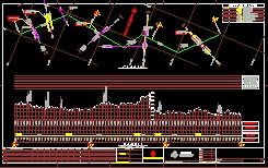
automatically the drawing of the geometric project of pipelines. By reading
data files the application draws the plant view, and the vertical profile
of a pipeline. Full annotation is added automatically regarding segment
lengths, magnetic orientation, horizontal deflection angles, integer kilometers,
coordinate system grid and north symbol. Besides rivers, high-tension lines,
roads, railways and property boundaries that crossing the pipeline are
also drawn.
A pipeline is a series of
|
operation
The user type DUCT at the
AutoCAD prompt and the application starts. The application reads the geometrical
information from three previously written data files and asks the length
to draw. The operation sequence is listed below:
 |
Command: DUCT
Name of the data file name for PLANT <pll01.csv>: pl01.csv Name of the data file CROSSING <cros01.csv>: cros01.csv Name of the data file PROFILE <pro01.csv>: pro01.csv Reading data of pl01... Read data from: 0.0 until the: 9043.03 Start at: 1500 Length to draw: 3000 |
At this moment the application start to draw automatically the whole drawing.
the plan view
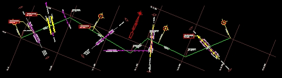 |
The magnetic grid (and all the plant drawing) is oriented automatically in order to place the drawing in the best way in the paper. |
crossings
 |
The application draws elements
that the pipeline crosses along its length, for example a high-tension
line. The application supports the following crossing types: legal right
limits, other pipelines, rivers, private boundaries, railways, high-tension
lines, roads and highways.
The application reads the information regarding crossings from an data file (SDF format ). At the left is showed a highway that the application draws when it reads from a the rows below contained in a data file. VIA,1+910.83,70:00:00,A
CUERNAVACA,A MEXICO,1+905,1+915
In the first row the highway is described. Seven fields separated by commas are used for this. The first three fields means a highway crossing at the point 1910.83m (measured over the pipeline length) and 70 degrees for the horizontal crossing angle with the pipeline direction. The next four fields are complementary texts for the highway drawing text annotation. The next two rows in the example are each one, an legal right limit of the highway. Notice the three main fields: (seperated by ",") identification, distance and crossing horizontal angle with the pipeline. Writing the crossing data file is much faster than drawing each crossing representation. |
the vertical profile
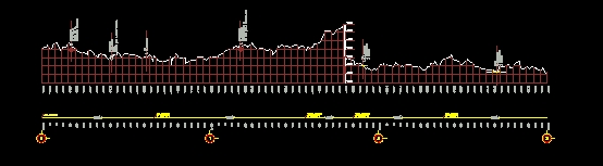
The profile is traced with the information contained in one data file previously written. At the right, you can see a few lines of an example for this leveling data file. The profile includes the crossings with graphic and text representation placed on the outline profile. Besides the drawing of the pipeline segments is included in the base with length and magnetic orientation and inflection points to be used as reference. When the application has to draw important points not contained in the leveling data file, like the z elevation where a high-line tension crosses the pipeline or elevation of regular stations, the z coordinate is obtained by interpolation. If some points of the profile
lie down or above of the reserved space to allocate the draw, the program
adjusts the drawing automatically by cutting and moving vertically these
points. Before to draw the outline of the profile, the program determines
the better reference level of the profile to obtain a profile with a smaller
number of cuttings.
|
0+356.86,-67.68 0+374.52,-69.10 0+380.14,-68.14 0+381.67,-69.57 0+393.59,-71.18 The fields in the data file are coma delimited (SDF format). Each row in the file is one point (x,z par) from a leveling survey. The first field is the horizontal length measured along the line and the second is the high (z coordinate). Any interval between these points is allowed and this interval can be different between points. The distance between the first and second point in the example is 356.86-340.00 = 16.86 m and the second interval is 17.66m |
The application requires
read three data files: horizontal polygon data file, vertical leveling
data file and crossings data file
These data files are SDF
formatted. They are plain files (without print format), and look like data
base files.
The data files can be produced
by text processors such as NotePAD or can be generated by third party software
(e.g. an EXCEL spreadsheet).