This page was created by my brother, Brent. If you're interested in
having him design something for you, yell at him at Brentronics
Web Design
Last Updated 9/9/97 BGD
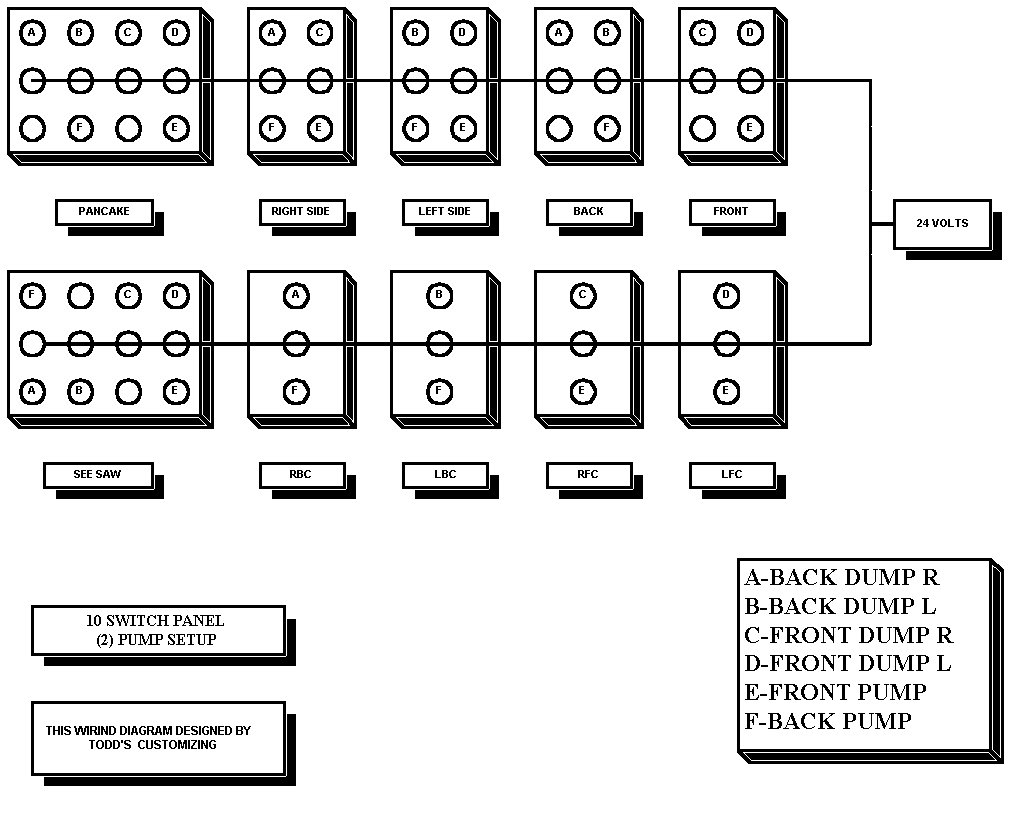
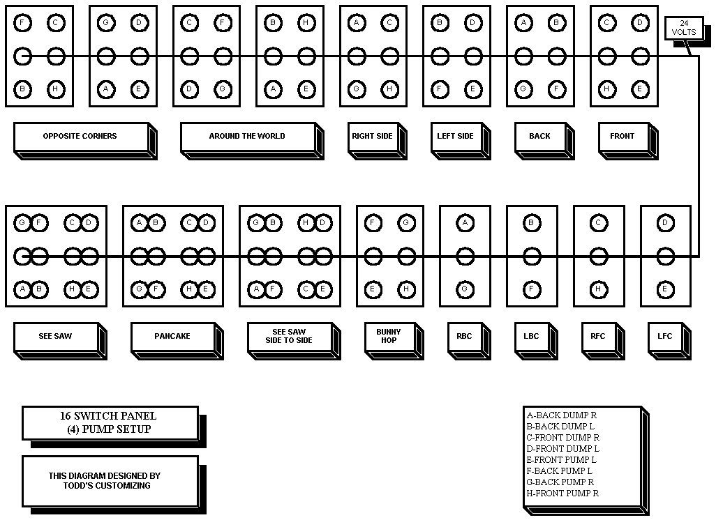
In the bottom right hand corner I have placed a box with the letters A thru F. Each letter represents where certain wires will go. On the switches I have those same letters in small circles. Those circles represent the terminals on the back of the switch. What you want to do is connect all the A’s to every A you see . Then all the B’s to B's and so on.
Once that is complete, you then need to connect the wires that come from the dumps, solenoids, and the 24volts off one of your batteries. As shown all the center terminals have 24 volts connected to them. What you end up having is small jumpers running from one switch to another. Make sure that you do this slowly and not connect the wrong jumpers or you could short out one of your switches.
This information is the same for the 16 switch setup as well as the 10 switch set up.
Click the links below to view my custom wiring diagrams for Switch Panels and Hydraulic Pump Setups.
This page was created by my brother, Brent. If you're interested in
having him design something for you, yell at him at Brentronics
Web Design
Last Updated 9/9/97 BGD