
A Complete Treatise on Installing Thrust Washers in the 1500 Engine
by Fred Griffiths
griffco@cadvision.com
griffco@cadvision.com
This is a tip from Fred Griffiths on how to replace them without pulling the engine. You might need to check out the tip on removing the pan without pulling the engine too.
Fred writes:
The greatest problem with the thrust washers in the Spitfire is probably the fear of replacing or repairing them! Until mine went that was my greatest fear. I had known they were worn, but was afraid to dig into the motor.
In case you are wondering, the thrust washers are two semi-circular metal pieces that fit over the crankshaft on either side of the upper half of the rear main crankshaft bearing. They are held up into a groove in the block by the bearing cap, and cannot be seen with the rear bearing cap in place - unless of course they are lying in the bottom of the oil pan. While they are doing their job, they ride against flanges on the crankshaft preventing it from moving forward or backward more than the specified amount.
The problem is that every time you press the clutch pedal, you push the whole crankshaft forward against the rear thrust washer. Starting the motor with the clutch depressed, or sitting at a stop light with the car in gear and the clutch pushed in causes even greater wear. Eventually it wears thin. When it is thin enough, it can slip past the rear bearing cap and drop out. Once it is out, the crankshaft can move further forward and the front thrust washer can follow the first one into the oil pan. Without the rear thrust washer in place, the flange on the crankshaft starts to wear against the bearing cap because it is thicker than the part of the block above it. This may be accidental, or a design feature of Triumph motors so the crankshaft flange can wear into the bearing cap before it wears into the block. Bearing caps are easier to fix than a block.
There are different degrees of thrust washer failures. The Haynes manual quotes crankshaft endfloat at .006" to .014" ( ie 6 to 14 thousandths of an inch), so it could be said that anything greater than 14 thou is failure. Assuming you want to replace the thrust washers at that point, before they wear completely out and drop into the oil pan, proceed as follows.
This article assumes the thrust washers are going to be replaced with the engine still in the vehicle. Place the vehicle securely up on stands or ramps to allow room to work underneath. Drain the oil and replace the oil pan drain plug. It will save you from getting oil dripped up your sleeves.
Remove the 1/2" oil pan bolts which are hidden under the front crossmember first, on the assumption that if they come out, the rest will come out easier. For those two bolts you will probably need an open/ring end wrench. Or, once the lock washer has broken loose, you may be able to use a 3/8" drive socket with flex joint. I know a 1/2" drive will not fit. Remove the other oil pan bolts, leaving one loose in the centre of each side until last. On the chance that the gasket sealant does not hold the pan in place, this prevents it from dropping unexpectedly on your head.
With all the bolts out, remove the oilpan down and backward. It just fits around the cross member when the crankshaft is in the correct position. If the oil pan jams, it will be because a counterweight or connecting rod journal on the crankshaft is 'down'. Turn the motor by hand 1/4 turn and try again. When the counterweight and journal for #1 piston are horizontal, the pan slips out easily.
Now, remove the two 5/8" bolts of the rear crankshaft main bearing cap. Wiggle the bearing cap straight down. If it sticks, there is a threaded hole in the bottom centre where you can screw in a bolt finger-tight to act as a handle. Put the cap aside in a clean place for later inspection.
Assuming the thrust washers are still in place, pry the crankshaft fully forward, then use a small pointed tool or stiff wire to push up on one end of the front washer. It will be easier to remove the front one first because the front flange face of the crankshaft will still be flat. The washer will rotate around the crankshaft and drop out on the floor. Push or pry the crankshaft fully back, and push our the rear washer.
Check the crankshaft flanges for wear. The rear one will be likely worn most. If it is still smooth with no bits of thrust washer metal seared onto it, all is well.
Slip a new thrust washer into the rear position. Push the crankshaft forward and slip a new washer in the forward position. Washers come in standard thickness, and .005" and .015" oversize (ie thicker). Pick a combination of these to allow the crankshaft the specified endfloat. Checking this endfloat can be done in two ways. The simplest is to push the crankshaft fully forward, and use feeler guages to determine the space betwen the front washer and the crankshaft flange. Make sure the washers are up where they will be when the bearing cap is replaced. The second method involves using a dial guage clamped to the motor block. With the crankshaft pushed fully one way (back or forward) set the dial guage against a bearing journal or counterweight and zero the dial. Push the crankshaft fully the other way and read the guage - it should be between the 6 and 14 thousandths of an inch. If it is, your work is done. Skip to the bearing cap replacement section.
However, if your thrust washers were worn to the point that they ended up in the oil pan, you may still be lucky - then again you may not. If the crankshaft has worn into the bearing cap, but has not scored the flange of the crankshaft itself, the motor may be repairable. If it has worn deeply into the cap, and just started to wear into the block above the crankshaft, but again has not scored the flange, this too may be repairable. If however it has worn deeply into the block where the thrust washer should sit, or has burnt or scored the flange of the crank - not easily repairable. Although I understand anything is repairable with enough money.
Working on the assumption that the crankshaft and block are in good shape, but the bearing cap is worn, you can proceed as follows. The fact that the bearing cap is wider that the corresponding piece of the block above it is important because it is this width that keeps the thrust washers in place. Now that the bearing cap is worn narrower on the rear side, it must be rebuilt to its original thickness.
Remove the bearing shell and inspect the bearing cap. One side, the front, should be flat with original machining marks visible. The rear side may have a lip of metal with original machining marks, just outside the worn area. From this original metal you can determine how much the crankshaft wore into the bearing cap, and how much to rebuild it.
To do this I used a lathe and small milling machine (a drill press may work). Also have on hand a piece of plastic about 1/2" to 3/4" thick and about 3" square, new thrust washer sets (various oversizes would be best), small brass countersunk machine screws, a tap to match the screw threads, small drill bits, and feeler gauges. (I tried using Plastigage. This is a fine filament of plastic compound extruded to a very precise diameter. When it is squashed flat between a bearing and crankshaft, its squashed width can be compared with a guage on the package to tell you the precise clearance between the shaft and bearing within a thousandth or two of an inch. However I found that I could not force the crankshaft hard enough against the thrust washers to squash the Plastigage - even using a foot long pry bar!)
First I took the plastic square and marked the centre. I could have used almost any material, perhaps even wood, but happened to have Lexan handy. It machines well, and is soft enough not to mark the bearing cap. I drilled a hole in the centre of the Lexan. The size is not important, but needs to be large enough to hold the Lexan in the lathe and later on the milling (or drill press) table bed. 5/16" should do.
Mount the Lexan square between lock washers on a bolt in the lathe chuck. Turn it down until it is round and fits perfectly in the semicircular bearing cap. Remove it from the lathe and bolt it down onto the milling table.
Then I laid the bearing cap on the milling table and brought it against the Lexan circle. Directly under the milling bit, position the bearing cap so that when it is rotated by hand around the Lexan circle the bit will mill out the worn area flat and square.
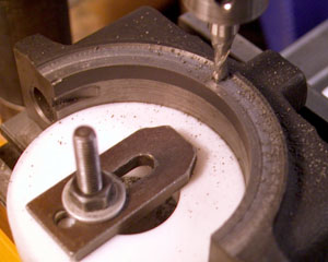
Adjust the position of the bearing cap (and Lexan circle) so the milling bit makes a recess in the cap exactly equal to the size of a new thrust washer. Do not mill the recess any deeper than necessary to clean up the wear. The recess can be milled deeper later if necessary. In the meantime, leave the milling machine setup untouched, you will need to use it again.
Since a fully circular thrust washer would have less pressure per square inch on it, it would wear more slowly than a semicircular one. Therefore it may be possible to machine the bearing cap recess to the exact depth to allow a new thrust washer sitting in there to be in the same plane as the washer recessed in the block above it. This depth cannot be determined mathematically, so may be decided by trial and error.
Once the recess is milled in the end cap, lay a new thrust washer in it and mark it in 3 places. (Remember the grooved side of the new washer will be out, away from the bearing cap. Don't go by parts manuals and catalogues that show them with the oil grooves against the block!)

Making sure the thrust washer does not move, drill the holes through the washer into the bearing cap. Remove the washer and tap the drilled holes to match the machine screws. I used #4-40. On the washer, countersink each hole enough so that the head of the screw is recessed in the washer. In this way, when the washer wears, the head of the screw will not wear off. You may also have to file the head of the screw down some. Also, by using brass screws, if the washer should wear down, the brass will not harm the crankshaft flange.
Now comes the trial and error and the feeler guages. (If you have access to a dial guage, it would work easier.) Fit the upper rear washer and push the crankshaft fully forward. Measure the space between crankshaft flange and the block where the front washer would go. You may need to use a steel block plus feeler guage. Make note of the measurement. Remove the upper rear washer. Fit the new lower washer to the end cap, but do not use any thread lock compound. Then fit the bearing cap, with its new thrust washer screwed to it. Tighten the bolts snug, but not torqued. Check the gap left for the front thrust washer again. If the two measurements are identical (not likely!) you are ready to reassemble the engine.
However, now you have two possibilities. If the measurement given when the upper washer was in place was greater then when the lower one was in, try a thicker washer in the upper until the measurements are equal.
If the thickest washer still doesn't give equal measurements, you could shim the lower washer with shim brass. Cut a shape identical to a thrust washer, lay it in the recess milled in the bearing cap, and drill or punch holes for the screws. Place the modified thrust washer on the shim material and screw it to the bearing cap. Again with trial and error test the clearances in the motor.
If the lower washer was pressing harder, you will need to mill the recess deeper in the bearing cap. Remove the new washer from the bearing cap and put the cap on the milling machine again. If a lot of metal needs to be removed, adust the mill chuck closer to the table. If only a few thousandths of an inch need to come off, try this.
Place the bearing cap on a piece of paper on the milling table. Cut a semicircle out of the paper to match the Lexan circle. This will raise the bearing cap a few thousandths of an inch. Mill off the extra metal, re assemble the washer and cap and re fit it to the motor.
Another method of making a thrust washer thinner is to grind it. Lay a piece of wet and dry emery paper on a hard flat surface. Lay the thrust washer HARD flat side down on the emery. (The grooved soft side is the thrust side - do not grind this side.) Rub the thrust washer in various patterns around on the emery to get even grinding. Check the washer thickness regularly by using a micrometer on at least three places. As I said this is the trial and error part. It may take several tries to get it correct or even close. If there is a difference of a few thousandths between the top and bottom washers, I would not worry. When one wears down by that amount, then the thrust will be taken by both washers and the wear rate will slow down. When the clearances are to your satisfaction, apply thread lock compund to the small brass machine screws and assemble the cap and washer for the final time.
For the final refitting of the bearing cap - Fit the bearing shell into the bearing cap, noting that it goes in the correct way around. Oil the bearing shell. Oil both front and rear thrust washers and install them into the motor. Note that the grooved side is the side which must face the the flanges of the crankshaft. Install the bearing cap into the motor as before.
Install the bearing cap bolts and torque them to the required number - Haynes says 40 ft/lbs. Apply gasket compound to the now clean oil pan and fit a new gasket. Compound the other side of the gasket and refit the pan to the motor.
Add motor oil and start 'er up. Remember - transmission in neutral and foot off the clutch pedal for longer thrust washer life!
This page hosted by ![]() Get your own Free Home Page
Get your own Free Home Page