ORGANIZATION OF THE USS INDIANA (BB-58)
ORGANIZATION
The Battleship Indiana (BB-58) organization was divided into nine main Departments as follows:
EXECUTIVE
NAVIGATION
GUNNERY
HULL
COMMUNICATION
ENGINEERING
MEDICAL
SUPPLY
CHAPLAIN CORPS
COMPLEMENT
Each of the departments was headed by a Commander or a Lieutenant Commander. The ship was further sub-divided into a total of twenty-eight divisions, one or more divisions in each of the nine departments. The total complement varied during the course of World War II from a low of 1,831 on 30 Sep 1942 to a high of 2,196 officers and men on 30 Jun 1944. There was a complement of 1,944 officers and men in the September, 1945 Cruise Book from which the following division numbers were obtained.
EXECUTIVE
The Executive Department consisted of the Executive Officer, the Personnel Officer and two divisions:
EX-1 = 31
EX-2 = 11
NAVIGATION
The Navigation Department was headed by the Navigator and had one division:
N = 34
GUNNERY
The Gunnery Department was headed by the Gunnery Officer and had three units in addition to the gunnery divisions; Combat Information Unit, Aviation Unit, and the Marine Detachment.
Gunnery Divisions
01 = 119
02 = 103
03 = 114
04 = 128
05 = 124
06 = 145
TDD = 07
FA = 50
FM = 65
Combat Information Unit
I = 61
L =64
Aviation Unit
V =17
Marine Detachment
07 = 74
HULL
The Hull Department was headed by the First Lieutenant and had one division.
R = 87
COMMUNICATION
The Communication Department was headed by the Communications Officer and had three divisions
CR = 66
CS = 44
CY = 23
ENGINEERING
The Engineering Department was headed by the Engineering Officer and had four divisions
A = 82
E = 110
PA = 90
PF = 103
MEDICAL
The Medical Department was headed by the Medical Officer and had one division
H = 35
SUPPLY
The Supply Department was headed by the Supply Officer and had three divisions
S = 84
SO = 37
SS = 35
CHAPLAIN CORPS
The Chaplain Corps consisted of a Roman Catholic Priest and a Protestant Minister.
RESPONSIBILITIES
Each division had two overall responsibilities; (1) routine responsibilities under normal sailing conditions, which included housekeeping and maintenance of assigned berthing and battle station areas, and (2) battle station responsibilities under battle conditions.
The Executive Department with the guidance of the Captain and the Executive Officer was responsible for the administration and all operational aspects of the ship. The Executive Department consisted of Yeoman, Buglers, Bandsmen, Photographers, and Sergeant-at-Arms
EX 1 Division
 Overview
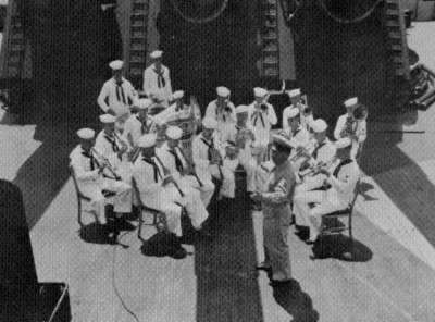
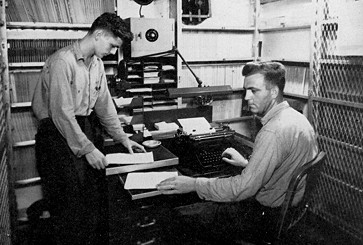
The EX 1 Division consisted of the Personnel Officer, Yeomen, Buglers, Photographers, and the 21 member band.They were responsible for routine correspondence, congressional correspondence, maintenance of the service records of all officers and enlisted personnel, maintenance of identification cards for all ships personnel, maintenance of liberty cards for all ships personnel, administrative matters for Court Martials and Captain's Masts, administrative matters for promotions and demotions, published a Plan-of-the-Day for each day, performed adminstrative duties for other administrative matters as needed.
EX 2 Division
Overview
The EX 2 Division consisted of the Master-at-Arms and his ten assistants. They were responsible for the law enforcement on the ship.
 The Navigation Department was responsible for the location of the ship and the course, speed and direction. The Navigation Department consisted of Navigators, and Quartermasters
N Division (Navigation)
 Overview
N Division had a complement of 34 officers and men and steered the ship at all times, responsible for celestial navigation at sea, stood watches on the bridge, maintained a running log of all activities on board, kept log of changing weather conditions and entered in ships log, maintained the ships chronometer used for celestial navigation, maintained and corrected all ships clocks, corrected charts, kept current all pilot directions, plotted coastal waters, and in port stood quarter deck watches and logged all shore side activities.
Complement
The battle stations of the 34 officers and men of N Division were as follows:
Primary Conn (Battle 1)
Secondary Conn (Battle 2)
After Steering Station
Chart Room
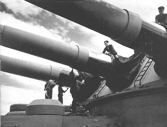
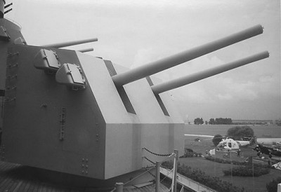
 The Gunnery Department was responsible for the loading, aiming and firing of the main battery of nine 16-inch guns, the secondary battery of twenty 5-inch guns and the forty-eight 40 mm and fifty-one 20 mm anti-aircraft guns. (For additional information regarding the armament, including cut-away views of the turrets, visit the Armament Page of USS Washington BB-56. Although the USS Washington was a different class of battleship, the armament on the Washington was similar to the Indiana's.) The Gunnery Department consisted of Gunners Mates, Boatswain Mates, Fire Controlmen, Radarmen, Pilots, Aviation Machinists and Marines assigned to thirteen divisions:
01 Division
 Overview
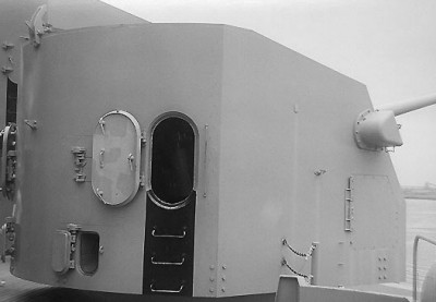
1st Division was responsible for the area of the main deck, including Turret 1, forward of a line between Turret 1 and Turret 2 to the stem of the ship. The division consisted of a deck crew of chief, first, second and third class (coxswain) boatswain's mates and first and second class seaman; a gun crew of chief turret captains, first, second and third class gunner's mates, and gun strikers. The gun crew was responsible under the division officer stationed in the turret for the operation of the turret under battle conditions and maintained the turret, hoists, and lower handling rooms under normal sailing conditions. The deck crew was responsible for the maintenance and operation of their area of the main deck. This included docking and undocking of the ship, taking on food supplies; receiving, removing, and transferring ammunition, airing bedding and other housekeeping chores. The deck crew provided the bulk of the turret crew for drill and battle station activities. The deck crew assisted the gun crew in the operation of the lower handling rooms, the transfer of the shells and powder bags from the handling rooms upward to the main part of the turret.
02 Division
 Overview
2nd Division was responsible for the area of the main deck, including Turret 2, from between Turret 1 and Turret 2 aft to the forward end of Turret 3. Their responsibilities were similar to 01 division, but in their assigned area of the ship.
03 Division
Overview
3rd Division was responsible for the area of the main deck, including Turret 3, from the forward end of Turret 3 to the stern of the ship. Their responsibilities were similar to 01 division, but in their assigned area of the ship. This also included the the launching and recovery of the small boats, refueling and other high line operations, crane duties in the recovery og the OS2U's, and ship maintenance.
04 Division
 Overview
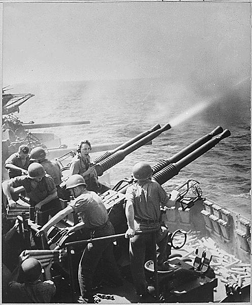
4th Division had a complement of 128 officers and men and was responsible for all of the forty-eight 40 mm/56 caliber Bofors guns. They were located in twelve quad batteries.
 Complement
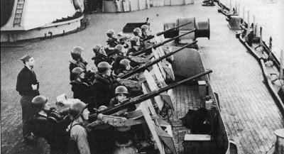
The man in the center top position is the 40 mm gun captain, coordinating the crew. On the far right is the trainer. The pointer, mostly cut off is on the left side of the picture. The pointer controls elevation of the guns, and the trainer the azimuth. Either can fire the guns. Normally, they do not aim the guns. The guns are aimed and moved electronically, controlled by a Mark 51 or a Mk 52 director and later in the war by a Mark 577. The other eight men in the picture are responsible for loading the gun and passing ammunition. The gun tub splinter shields surrounding the quad 40s were filled with storage racks for ready rounds.
There were 12 quad 40 mounts on board. In addition to the eleven men in the picture there were,
for each of the quads, an additional 8 guys passing ammunition from storage, 2 guys standing by
in case the electronics or the motors broke down, and another operating the 40 mm gun director.
05 Division
 Overview
5th Division was responsible for the five Mark 28 twin 5 inch gun mounts on the starboard side of
the ship. The division consisted of a deck crew of first, second and third class (coxswain) boatswain's mates and first and second class seaman; a gun crew of first, second and third class gunner's mates, and gun strikers. The gun crew was responsible for the operation of the gun mounts under battle conditions and maintained the gun mounts and lower handling room under normal sailing conditions. The deck crew was responsible for the maintenance and operation of everything on the second deck on the starboard side. This included operating the crane and boats; taking on fuel and refueling other ships; docking and undocking; taking on food supplies; receiving, removing, and transferring ammunition, airing bedding and other housekeeping chores. The deck crew provided the bulk of the gun crews for drill and battle station activities. A gunner's mate was mount captain and the deck crew assisted the gun crew in the operation of the lower handling rooms, the transfer of the projectiles from the handling rooms to the mount, and the firing of the 5-inch projectiles.
Personnel in One Mark 28 Twin Mount
For the number and types of personnel in one 5"/38 twin mount let's start at the top and work down. In the mount itself there was a gun captain, 2 shell loaders, 2 powder loaders and a pointer and a trainor for a total of 7. In the upper handling room, just below the mount, there were 2 shell handlers (setting the fuses), 2 powder handlers and the room captain for a total of 5. In the lower magazines there were 4 shell handlers and 4 powder handlers as well as the magazine captain for a total of 9.
That's 21 men for just one of the ten 5"/38 twin mounts. Six more personnel, which came from the FA Division, can be added for each of the four fire control directories.
06 Division
 Overview
6th Division was responsible for the five twin 5 inch gun mounts on the port side of the
ship. Their responsibilities were similar to 05 division, but on the port side of the ship.
07 Division (Marines)
 Overview
7th Division was the U S Marine Corps detachment on the Indiana. The detachment had a complement of approximately eighty men including one Captain, two Lieutenants, one top Sergeant, two Gunnery Sergeants, two Platoon Sergeants, four Buck Seargeants, eight Corporals, and approximately forty to fifty Private First Class, the balance were Buck Privates. Two Field Music (buglers) and two Cook rates completed the detachment.
Duties
Their duties included standing brig watch, Captain's and Executive Officer's orderlies, two buglers who stood watch on the bridge underway and quarter deck in port, two cooks who stood watch in the galley. Their battle station was to man some of the fifty-one 20 mm/70 caliber antiaircraft guns. Twenty millimeter machine guns were air cooled, the guns cool better and use less if short bursts are fired. There is a tube of water on the outside of the splinter shield, and asbestos gloves were provided to handle the hot barrels. An overheated barrel, or one with a round stuck in it, could be cooled down while a spare barrel was used. In combat full magazine bursts can be fired, but first the gunner had to learn to hold the target. The forty millimeters were water cooled (Prestone). If their firing rate was set low, 114 rounds per minute, they would not overheat.
The marine detachment went ashore as part of the Yokosuka Landing Force, Task Force-31
FA Division (Fire Control Anti-aircraft)
 Overview
FA Division had a complement 50 officers and men and was responsible for the tracking, plotting, firing, fine adjustments, and overall fire control of the twenty Mark 12 5-inch/38 Caliber multi purpose guns that constituted the secondary battery. They operated the four Mark 37 secondary fire control directors Sky One (forward), Sky Two (port side), Sky Three (starboard side), and Sky Four (aft), manned the Air Defense Station near the top of the main control tower, as well as the secondary battery plotting room below decks in the middle of the ship. With the Mark 37 Director and the Mark 4 radar (used by the South Dakota on 26 October 1942 when it shot down 26 aircraft on one day) they had a system also suited for surface targets, perfectly matching the excellent dual-purpose capabilities of the 5-inch 38 gun. In addition to controlling the fire of the 5-inch mounts FA Division also had the option of controlling the twelve 40 mm quad mounts, staffed by 04 Division, when they were not in local control, particulary useful in night engagements. Also FA Division was responsible for the unloading of the 5 inch shells from lighters.
Complement
The battle stations of the 50 officers and men of the FA Division were as follows:
Sky 1, 2, 3, and 4. Each of the four Mark 37 Secondary Battery Directors had 6 personnel from FA division. Control officer, talker, rangefinder operator, range talker, trainer, and pointer.
Air Defense Station. Air Control, near the top of the main control tower, was staffed by 5 personnel from the division
Secondary Battery Plot. The balance of the division personnel were in secondary battery plot
Mark 37 Director System
The Indiana used the optical/radar Secondary Battery Fire Control System utilizing the Mark 37 Secondary Battery Director that was first tested in 1939 and became the wartime dual purpose director in use by all US Navy ships that had 5 inch 38 batteries, could structurally support the Mark 37 Director and had room below decks for a secondary battery plot. Because it incorporated elements remote from the rotating director Mark 37 was designated a 'gun fire control system' rather then a 'director'. The Mark 37 system is based on a 15-foot long Mark __ stereoscopic rangefinder with two Mark 69 telescopes, one for the trainer and one for the pointer, and a Mark 29 scope, later a slewing sight, used by the control officer to scan for other targets. Atop the shield was a Mark 4 radar antenna and later in the war a Mark 12. In 1943 a single vertical parabolic oscillating Mark 22 radar antenna was added to the right of the of the Mark 4 or Mark 12 antenna. The Mark 22 oscillated up and down to determine the height angle of incoming aircraft. Thus, range, bearing, and altitude could be obtained. The Mark 4 or Mark 12 radar and operators were located in Secondary Battery Plot. Also, the system had a Mark 6 Stable Element in Secondary Battery Plot. The system is completed by the Mark 1 electro-mechanical-analog range keeper also located in Secondary Battery Plot. It incorporated a horizontal rate of 400 knots and a vertical rate of 250, which proved sufficient until the kamikaze attacks by Baka bombs late in the war. The Mark 1 range keeper had high speed controls, and a fully automatic rate control in the computer which could reach a target solution without operator aid. There were four Mark 37 systems one for each of the four Sky Directors.
Air Defense Station, near the top of the main control tower, was manned by the Air Defense Officer (an Assistant Gunnery Officer) and his assistants. Airborne target selection was made by him. He directed and assigned airborne targets to specific sky directors as required. At one time three airborne targets simultaneously and from different locations made a coordinated attack on the Indiana that was successfully repulsed with the loss of all three aircraft.
FM Division (Fire Control Main Battery)
 Overview
FM Division had a complement of 65 officers and men and was responsible for the tracking,
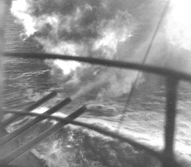
plotting, firing, fine adjustments and overall fire control of the nine Mark 6 16-inch/45 Caliber guns that constituted the main battery. They operated Spot 1 at the top of the main control tower, Spot 2 at the top of the aft control tower, had personnel operating range finders and Mark 7 range keeper computers in each of the three turrets and manned the main battery plotting room below decks in the middle of the ship. With the Mark 8 Radar they could begin tracking surface targets at 64,000 yds. (32 miles) and begin firing at 42,000 yds. (21 miles). This system also permitted accurate surface fire under complete radar control during night engagements, an inestimable advantage over optical systems. Also, they were responsible for the offloading of powder bags and 16-inch shells from lighters.
Complement
The battle stations of the 65 officers and men of the FM division were as follows:
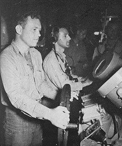
Spots 1 and 2. Each of the Mark 38 main Battery Directors had six personnel from the division. A director officer, a talker, a pointer, a trainer, a rangefinder operator, and a range talker.
Turrets 1,2,&3. Each of the three turrets had four personnel from the division. A range finder
operator, an assistant range finder operator, a talker, and a computer operator to operate the
electro-mechanical-analog rangekeeper computer.
Gunnery Officer Station. The Gunnery Officer's battle station was the top level of the conning tower. On top of the conning tower roof was mounted a 15 foot Mark 40 director spotting glass/auxiliary main battery range finder as well as two periscopes to use in surface target spotting and selection. Later in the war the spotting glass/range finder and periscopes was augmented first with a Mark 3 and later with a Mark 27 radar antenna. The station was manned by the Gunnery Officer, most of his assistants and two FM Division personnel.
Main Battery Plot. The balance of FM division personnel were in main battery plot
Background
The Indiana used the optical/radar Main Battery Fire Control system utilizing the Mark 38 Main
Battery Director developed early and in use by all the fast battleships during WW II and still
operational for Desert Storm. The following is a somewhat simplified fire control tutorial. Fire
control against a moving surface target is quite different from fire control against a land target.
With the former, you are trying to determine the target's position relative to your own ship, with
allowances for the course, speed, and likely evasive maneuvers your own ship and the target will
make. With the latter, the target's location is known, and you need to accurately plot your own
ship's position in relation to it on a simple grid.
Mark 38 Director System
The main functions of the Mark 38 Director System were to obtain target bearing, level angle and cross level, as well as target range. The Mark 38 Director System was based on the 26.5 foot long Mark 48 stereoscopic rangefinder, with two Mark 69 telescopes, one for the pointer and one for the trainer, a Mark 56 telescope for the crossleveler, and a Mark 29 scope used by the spotter to scan for other targets. Atop the shield of the director was a narrow band Mark 13 radar antenna that scanned down the flight path of the
shells and provided the range to the target. The Mark 13 radar and its operator was located in Main Battery Plot. Repeat radar scopes were located in the directory for use by both the pointer and the trainer. In addition the system had a Mark 43 Stable Vertical in Main Battery Plot. The system was completed by the Mark 8 electro-mechanical-analog range keeper computer also located in Main Battery Plot. Together the optics and the radar provide range and deflection information for a target, and fall-of-shot information based on the shell splashes. This system was optimized for fire control against another surface ship. The Mark 38 director could be trained by hand or power (local or automatic).
Surface Target
At a height of 116-feet above the sea, the range for the optical fire control for a target at sea
level is 22,000-26,000 yards (about 11-13 miles) the distance to the horizon. Against a target only a few feet tall, or sunk into the ground like a bunker, this system is far from ideal. But if the tallest part of the target is a ship's mast say, 65 feet above sea level, then the Mark 38 rangefinder can see the target at over
21 miles. This system is brutally accurate in a surface fight, as the gun elevation and train data is generated by the remarkable Mark 8 electro-mechanical-analog range keeper computer, located in Main Battery Plot. The course and speed of your own ship is automatically fed in, along with the distance (range from both the optics and the radar) and deflection (relative bearing from the course of your own ship) to the target. The expected course, speed and maneuvers of the target are fed in by hand. When the hand imputed target course and speed is properly selected the computer generated range and bearing will match the actual. Other input includes meteorological data like wind speed and direction, stabilization data, shell type, charge type, and individual gun ballistic data, and the mechanical computer even takes into account how far the Earth will rotate while the shells are in the air.
Shore Target
For shore bombardment beyond visual range (the Battleships in Desert Storm fired on targets up
to 20 miles away), the Mark 8 electro-mechanical-analog ballistic rangekeeper computer is utilized. Two shore bombardment systems can be used. The first, sometimes called the 'offset method' is used to determine the position of the ship on a grid laid out on a bombardment chart. Either the ship's range and bearing in relation to a known landmark on the grid (tower, tall building, lighthouse, etc) is used, or the ship's position is plotted by navigational methods and course and speed over time are factored in. At Iwo Jima Mount Surabachi's crater was used as a known landmark and at Okinawa the Naha Lighthouse was used.
With the first shore bombardment system, the Spot One Mark 38 Directory is used to provide 'target' data by staying trained on the landmark, which locates the battleship on the grid by working backwards from the fixed target. Range and bearing to the desired target is determined from the bombardment chart. This information is fed into the Spot Two Mark 8 Rangekeeper in Main Battery Plot and used to generate turret train and gun elevation data. This information is supplied to the Spot Two Mark 38 Directory, which is automatically trained on the desired target, and the Spot Two Main Battery Plot System controls the firing.
With the second shore bombardment system, used in places like the desert where there are no handy landmarks, or where the exact position of the landmark on the grid is not precisely known, the Mark 38 Directory is not used. Either way, the fire support mission is called in by giving the target's location on the same grid.
In both cases the ship's crew need never see the target, as they are aiming for a grid coordinate and not the visible target itself. From the grid on the bombardment chart the range, bearing from ship, and target
height from sea level is computed based on the grid coordinates of both the ship and the target..
This information is cranked into the Mark 8 electro-mechanical-analog ballistic rangekeeper computer in Main
Battery Plot and used to generate the turret train and gun elevation data. A spotting round verifies that the guns are trained on the correct grid coordinates, and the forward spotter or remotely piloted aircraft is used to spot the fall of the shot. In the Gulf, the little RPV's proved to be most useful for finding targets and spotting the fall of shot.
I Division (Intelligence)
 Overview
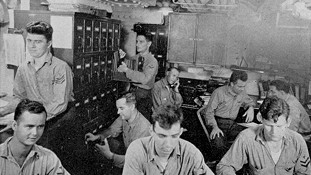
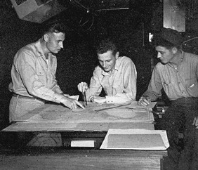
I Division was responsible for the location (bearing and range), tracking and identification of all surface and air-borne craft. They operated in the Combat Information Center located below decks in the middle of the ship. With the SK search radar they could detect aircraft at ranges up to 80,000 yds. (40 miles).
Orginally located behind the bridge and called "Radar Plot" its duties were primarily detecting and plotting air and surface contacts and information. In February 1943, primarily as suggested by Vice Admiral Lee, and during the collision repairs at Pearl Harbor, "Radar Plot" was greatly expanded to Combat Information Center and they were relocated below decks. Their functions were expanded to include extended navigation functions, increased information and suggestions to the bridge, radar counter measures, standby fighter direction, assisting the application of operational plans, weather tracking, and providing information to the bridge and command as requested.
USS Indiana Radar

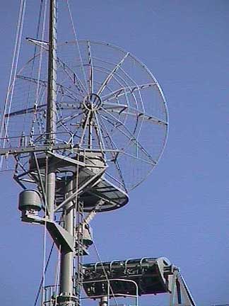 Forward Mast
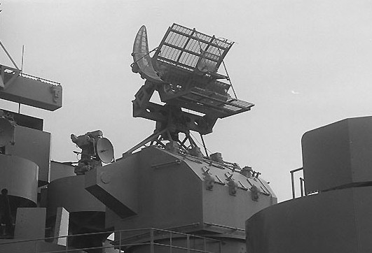
The big round dish is a SK-3 air search radar. Below the SK-3 are two smaller radomes. The left is a DBM radar direction finder used to locate and jam opposition radars. The other radome forward of the mast is a
TDY radar jammer. At the bottom and forward is a Mk 13 fire control radar mounted atop the Spot One Mark 38 director. The platform immediately below Spot One is Air Defense Station, the battle station of the Air Defense Officer
 Aft Mast
The large rectangular radar is a SR air search radar that had a tilting antenna. Behind it and above, the smaller curved radar is a SG surface search unit. Forward, the top of the SK-3 circular air search radar can be seen. Behind the flag on the forward mast, one can catch a glimpse of another small radome. This is an SU surface search radar.
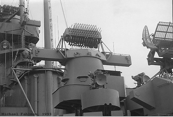 Fire Control Radar
Looking forward from port side aft. Spot 2 the aft 16 inch Mark 38 main battery gun director is immediately aft of the mainmast. Mark 8 main battery radar is installed on top of the 26 foot Mark 48 rangefinder. Below the Mark 38 is a tub with a Mark 57 director for a port side 40mm Bofors anti-aircraft quad. At the right of this director is a similar Mark 57 director for a starboard side quad. At the far right is part of Sky 4 the aft 5 inch gun Mark 37 secondary battery director with Mark 12/22 radar mounted atop. The Mark 37 director could also be used to control and direct the fire of the 40 mm Bofors.
L Division (Lookouts)
 Overview
L Division was responsible for the visual sighting of all ships around the Indiana to the horizon. They were responsible for the maintenance of the superstructure above the Captain's Cabin. During General Quarters they operated the 20mm on the main deck that the marines were not responsible for.
TDD Division (Drone Planes)
 Overview
TDD Division was responsible for the maintenance, repair, launching, and flight control of the six foot wing span model planes used to train the antiaircraft batteries. They were
launched from the scout plane catapults and were not recoverable.
V Division (Scout Planes)
 Overview
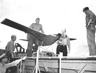
The Aviation Division or "V" Division as it was known, was on the fantail of the ship. V Division was responsible for operation and maintenance of the two Vought OS2U-3
"Kingfisher" scout observation seaplanes. This included the two catapults, and the launching and recovery of the aircraft.
Complement
The division of nineteen men, including four officers, maintained the two OS2U pontoon seaplanes mounted on the port and starboard catapults. Their battle station was Group 18, a 20mm gun station, on the port side aft of Turret Three.
Operations
The pilots flew th OS2U's with an enlisted man in the aft cockpit on missions. The scout planes were constantly being launched,sometimes as bombardment spotters (to supply revised range and bearings for the 16inch guns) and sometimes to rescue downed carrier airman. Aircrews on these float planes generally hated these launchings. The acceleration of the plane, blasted down the tracks by an explosion of gunpowder, sometimes caused the crew to blackout or lose consciousness. Recovering these planes was a little easier, the Indiana would steer a tight, partial circle (about 90 degrees), smoking float flares were thrown over to mark wind direction, and the Indiana's forward inertia would leave a "lake" of fairly smooth water for a few hundred feet behind for the plane to land on. The plane then taxied to a net, "sea sled", the bottom of the float was hooked onto the sled, and the sled and plane was pulled toward the ship's aft crane. The hook of the ships aft crane was attached to the plane by the planes crew and the plane with crew was lifted and placed back on the catapult.
One of the USS Indiana's Kingfisher planes was restored at the Paul E. Garber Facility in Suitland, MD., and is presently on loan to and may be viewed at the Palm Springs (CA) Air Museum.
The Kingfisher will be returned during the Fall of 2003 to the Air and Space Museum and will be on permanent display at the Steve F. Udar-Hazy Center, the National Air and Space Museum Annex at the Washington Dulles Airport in Chantilly, VA. The center is scheduled to be opened on 15 December 2003, the 100th Anniversary of Man's First Flight at Kity Hawk by the Wright Brothers.
Last Updated 02 July 2003

All the world's a stage