Description of Current Working Design
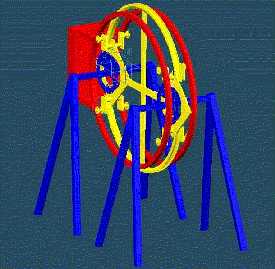
A picture of the Current Structure Built as seen through a Solid Edge Drawing program.
The picture above shows all the primary components of the walking robot. It will operate along the lines of the original design theory that I created. It was adjusted, however, so that it would be able to function in a 3-dimentional environment.
The two leg groups (in blue) consist of four camera tripod legs. They will rotate together via a chain that will be mounted on large gears that connect to each leg group through a combination full 360 degree revolute, and a 30 degree steering joint.
The Pendulum parts (in red) consists of two rings that are bolted to a large mass (25lbs+-5lbs). These rings rotate freely about 8 small bearing wheels (4 per ring, they are the color yellow on the main body). The pendulum will lock itself into position, after it has swung, by way of another chain wrapping around the circumference of the main body and resting in the chain guide ring (in yellow on the main body).
The main body (in yellow) consists of two hip rings, a chain guide ring, and bearings. The two hip rings act as a track for the two hip assemblies of each leg group. They also structurally support the 8 small bearing wheels (4 per side) that the pendulum rings ride on.
To deal with the issue of steering, the two leg sets (in blue) are on pivots that remain normal to the horizontal plain. I intend on placing steering servos at these points.
To deal with the issue of varying terrain under the feet of the robot, I have built into the current working model camera tripod legs that will slide to the apropriate height and lock into position with the aid of a designated motor.
The current motor list to be used in this robot model is as follows:
A. One -Overswing motor responsible in rotating one leg set over the weight bearing ones. It will be located on the main body (in yellow).
B. Two -Steering motors located onboard each rotating hip pivot (in blue).
C. Two -Leg unit (each leg unit being 4 camera tripod legs) locking/unlocking motor responsible for locking the legs at there individual heights once the legs all touch down. They will be located onboard the two leg units (in blue).
D. One -pendelum swing locking motor. This motor will be responsible for locking the pendelum into its end of swing positon, and releasing it for its pendelum swing phase of the travel. It will be located onboard the Pendelum itself (in red).
Total: 6 motors, simple and non-computer controlled (excluding the steering motors that are Radio Controlled.