If you want to ask me any questions, you can reach me at pocher_rolls@yahoo.com.
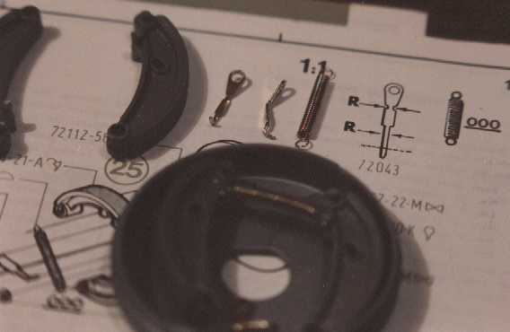
Now we continue with the most infamous part of this car, the brakes. As Brady Ward from www.scaleautoworks.com put it, "the most diabolical subassembly of all the Pocher kits." Here are the beginnings of the front axle brake shoes assembly.
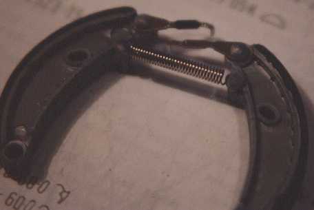
The instructions require you to cut the long length of spring into six smaller lengths (two for the front and four for the back axles) and bend the ends over to make eyelets that get heat flared onto the shoes. The next photo shows the spring for one pair of shoes on the front axle.
Problem was that the spring was too tight. At that tension, the linkage would have too much stress on it and would loosen up (the infamous pivot nuts on the front axle) or worse, bend or break something. I had to stretch the spring just a little to reduce the tension. Also, the actuating linkage had to be adjusted (bent) so the shoes would not touch the brake drums until about half way through the pedal travel (assuming I get the brakes to work). Little did I know that I should've left this alone until much later in the assembly. The actuating linkage is what is used to adjust the brake shoes after the chassis is assembled and the brake rods (and cables, you'll see more about this later) are in place. This will be covered in detail later.
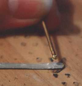
After everything worked and fit right, the pieces had to be heat flared onto the shoes. The instructions illustrate heat flaring with a drawing of the tip of a flat head screwdriver being heated by a cigarette lighter and the hot screwdriver melting the plastic part to flare it. Yea right. I prefer a little more control and consistency in my assembly. I wanted to make a tool that would allow me to use a soldering iron to give me a nice controllable flare. I started with a strip of aluminum. Then I took a round headed nail, machined the head a little to give it a more pronounced head. I placed the machined head against one end of the strip of aluminum and pounded a dish shape into it. To get a better idea of what I'm talking about, you really should look at the photos below.
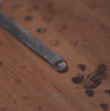
Next, I placed that tool over the post to be flared and applied heat with a soldering iron from the other side of the tool. This allowed me to control the amount of heat that would get applied and the shape of the flare. The key to flaring is that the piece is still supposed to move after it's been attached by this method.
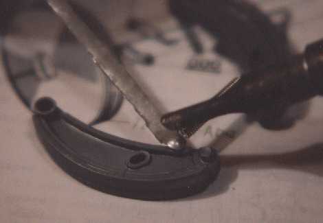
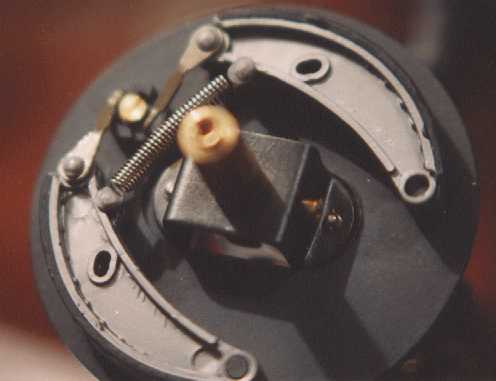
Here's the completed assembly ready to be installed onto the backing plate.
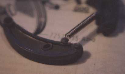
Once on the backing plate, it actually looks kinda cool.