|
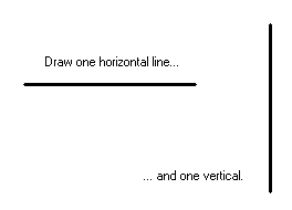
Writing programs that makes use of the joystick controller isn't all too difficult once we have a basic understanding of the interface. A standard joystick for the IBM PC is an analog device that consists of two potentiometers and two switches for the joystick buttons. To understand how this works, you can use a sheet of paper and draw two lines using a No. 2 pencil. Draw one line vertically and one horizontally. Do not intersect them!!! Instead, draw them as illustrated below.

|
If you happen to have an ohmmeter (or even know what one is) you could measure the resistance across the drawn lines. On the horizontal line, measure from the far left of the drawn line. On the vertical line, measure from the top.

|
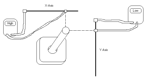
Even though I'm not the best artist in the world it should be adequate enough, I hope, to prove a point. You see on the horizontal axis, one of the probes is situated on the far left side of the horizontal line while the second probe is positioned at various places along that same line to get various readings on the meter. The same is done with the vertical line from the top. The farther the probes are moved apart, the higher the resistance value measured on the meters. As you can see the minimum value measured on the meters are measure when the roving probes are on the far left side of the horizontal line and at the top of the vertical line. The horizontal line can be thought of as the joystick's x-axis and the vertical line can be thought of as the joystick's y-axis.

|
This picture also depicts the position of the joystick in relation to the probes on the the two drawn lines. The joystick, like the drawn lines and probes, shows the highest amount of resistance on its x-axis when the stick is pointing to its farthest right position. Like-wise, the y-axis of the joystick shows the highest resistance when the stick is pointing farthest down. In the electronics community, resistors that vary their resistances like that are called potentiometers or pots. We can say that joysticks have two "joystick pots," one for the x-axis and one for the y-axis.
Just as our picture above illustrates, it is possible to get the resistance values of the joystick pots using an ohmmeter and by probing the right pins on a joystick's plug. When the joystick is plugged into a PC, the pot values are measured by the computer and integer values are derived. (Whenever you see the term "joystick pot value," we're referring to the resistance value of the joystick pot.)
Send your questions, comments, or ideas here.