Open Source Baseband Bluetooth Core
Under Construction
The aim of this project is to develop a synthesizable Bluetooth cores and software stacks
If you have any comments please email
me.
Introduction
Notes:
This project is one of OpenCores projects. You can download the latest vhdl source files from OpenCores CVS by using hte bluetooth module name.
Baseband main blocks
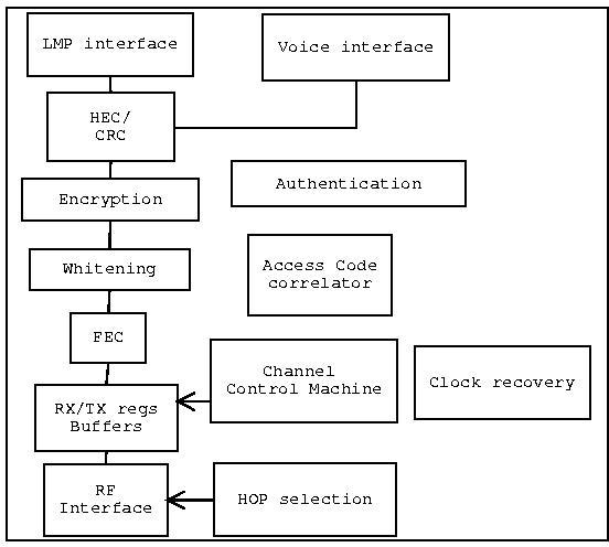
The baseband core (link controller) is composed of the following blocks
- RF interface
- LMP interface (a CPU may be)
- Hop selection controller
- ACL & SCO link controller
- HEC and FEC controllers
- Access code correlator
- Data whitening (Scrambling)
- Encryption
- Authentication
- Audio Interface
- Clock recovery and synchronization
- Channel Control Machine
- RX/TX buffers and registers
Baseband Block diagram
Bit stream flow
- Header: Header creation -> HEC -> scrambling (wightening) -> FEC encoding -> combining with scrambled payload.
- Payload: payload insertion -> [payload CRC] -> [Encryption] -> Scrambling (wightening)-> [FEC encoding] -> Header insertion
- steps between [] depends on the packet or link type.
- The scrambling is performed on both the header and payload and passed serially (header then payload) to the scrambler without reinitializing it
Header Error Check (HEC):
- This block is composed of two sub-blocks, one for HEC generation and one for HEC checking.
- It performs error detection and correction on the packet's header.
- It holds 8 bits of CRC of the header
- It is performed on the following 10 bits of the header AM_ADDR, TYPE, FLOW, ARQN, SEQN
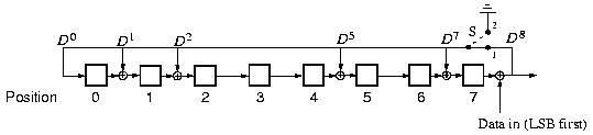
- The generator poly nomial is g(D)=D8+D7+D5+D2+D+1
- It is performed before the 1/3 FEC encoding of the header
- It participates in ARQN & SEQN control.
- It participates in the detection of the address because the UAP is used.
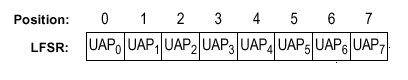
- The shift register is preloaded with the slave upper address part (UAP) in Master page response state.
- The shift register is preloaded with the default check initialization (DCI) which is 0x00 in the FHS packets sent in inquiry response.
- The shift register is preloaded with the UAP of the master device.
- LSB bits of the header are entered first.
- The LSB of UAP goes to the left-most shifter register element
- In the checking the shift register is initialized as before and HEC is performed on the header
HEC Generator Top Block diagram

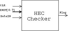
HEC Checker Top Block diagram
HEC register initialization
HEC core Block diagram
CRC:
- This block is composed of two sub-blocks, one for CRC generation and one for CRC checking.
- It performs error detection and correction on the packet's payload.
- It holds 16 bits of CRC of the payload
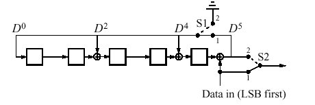
- The generator poly nomial is (CRC-CCITT) g(D)=D16+D12+D5+1
- It participates in ARQN & SEQN control.
- It is not performed on all types of packets.
- CRC is performed on the following ACL links packets DM1,DH1,DM1,DH3,DM5,DH5
- CRC is performed on the data part of the DV SCO link packets only
- CRC is performed on FHS packets
- CRC is done before any possible FEC encoding
- It participates in the detection of the address because the UAP is used.
- The shift register is preloaded with the slave upper address part (UAP) in Master page response state FHS packet.
- The shift register is preloaded with the default check initialization (DCI) which is 0x00 in the FHS packets sent in inquiry response.
- The shift register is preloaded with the UAP of the master device.
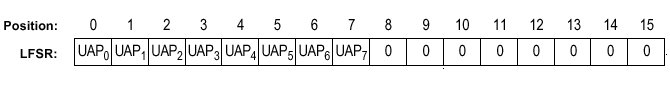
- Since the UAP and DCI are 8 bit values, they are loaded into the 8 least significant (left-most) and other bits are set to zero
- The CRC code is appended to the information.
- In the checking the shift register is initialized as before and CRC is performed on the header
- LSB bits of the data are entered first.
- The data bits are shifted into the LFSR and when they are finished the Switsh (S shown in the figure) passes zeros to the LFSR.
- The CRC and HEC blocks are very similar except that HEC must be done in all packets and it is 8 bits while CRC is done on some packets and is 16-bit
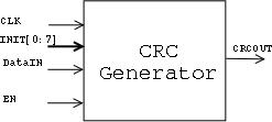
crc Generator Top Block diagram
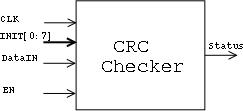
crc Checker Top Block diagram
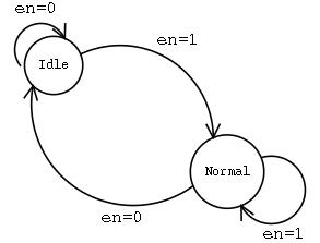
crc state diagram operation
crc register initialization
crc core Block diagram

CRC generator vhdl code
Radio Frequency Interface (RF):
- A suggestion to this interface is BlueRF protocol which is not finalized yet.
- If the BlueRF is ready on the time of implementation, it will be chosen for the RF interface core, else I have to select another interface.
- For more information about BlueRF email BlueRF mailing list
Data whitening
Data whitening is done in order to randomize the data from highly redundant pat-terns and to minimize DC bias in the packet.
- This block is composed of two sub-blocks, one for generation and one for reversing (data extraction)
- It is performed on the packet header and the payload (including the CRC)
- It is generated with 7 bit lfsr.
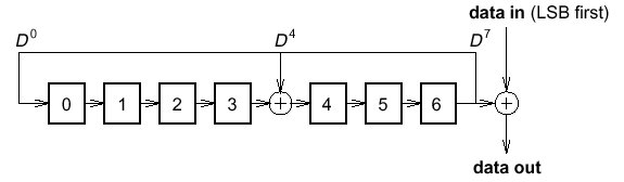
- The generator polynomial is g(D)=D7+D4+1
- The header and data are xored with the output of the LFSR.
- The shift register is preloaded with the master Bluetooth clock, CLK 6-1 ,extended with an MSB of value one. CLK1 is written to position 0, CLK2 in position 1 and so on.
- FHS packet sent during frequency hop acquisition, the X-input is used in inquiry or page response states which depends on the the 79-hop and 23-hop system (for more information read page 79 from bluetooth_core_1b standard)
- To descramble the header and data, the scrambled stream is passed on the same circuit.
Data whitening Top Block diagram

Data Whitening core Block diagram
Forward Error Correction (FEC) encoding
- There are two types of FEC, 1/3 FEC and 2/3 FEC
- It is used to reduce the chances of getting corrupted information
- It works by increasing the no. of transmitted bits which reduces the usable bandwidth available for the information.
- 1/3 FEC is used to protect the packets' header and some types of payloads are protected by 1/3 FEC, some by 2/3 FEC and some are not protected. Refere to section 4.6 from bluetooth core 1.0B standard
- 1/3 FEC is implemented by repeating the bit three times.
- 2/3 FEC is implemented using the LFSR polynomial g(D)= (D + 1)(D4+D+1)
- 2/3 FEC: each block of 10 information bits is encoded into a 15 bit codeword.
- 2/3 FEC: This code can correct all single errors and detect all double errors in each codeword.
1/3 FEC representation

2/3 FEC representation
Access code correlator
- Access code represents the start of the bluetooth packet
- It is composed of a preamble, sync word and trailer that gives 72 bits.
- The access code correlator is used to match the coming signal with a possible access code..
- A match pattern (access code) is used to match the coming signal.
- When the coming signal bits matches a specific no. of bits with the math pattern or exceeds it, it can be said that a start of the packet is found.
- A sliding window correlator is used that matches the signal from low to high with the access code from high to low.
- The slave can use the time needed to find the start of the packet to adjust its clock.
Correlator top
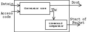
Correlator core

Clock recovery
LMP interface
Rx/TX registers
Hop Selection
Voice Interface
Link Controller Machine
Looking for..
- An RF interface between baseband chip and RF chip
- An LMP interface between the baseband chip and higher level protocols and chips.
Last update 13 January 2001
