Frequency Expansion
1) This is one of the more difficult mods out there.
2) Open the bottom cover of the radio .
3) Find the PLL Board. Its the one with the 64 pin chip on it.
4) At the front of this board by the PLL chip ther are 2 resistors R540 and R539.
5) Cut them.
6) Close the radio up. Turn it on.
Tweak and Peak
Audio limiter - R247RIT Modification
AM Power - VR 111
SSB Power - VR 103
1)Remove top and bottom covers.Aligning the RIT
2)On the top of the main board find D140.Cut it.
3)Solder one end of a 10 OHM resistor to the location in the picture below.
4)Take a 7.5v zener diode and solder the end without the band to the small brass shield.
5)Now solder to other end of the diode to the open end of the resistor.
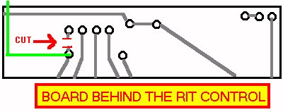
6)Find the PC Board that is behind the RIT Knod
7)Cut the trace as you see in the picture above.
8)Solder a wire(See the green wire in the pics) from the point that the diode and resistor meet togeteher to the bottom of the board where you made the cut.
1)Place the radio so that the smaller PC Board is facing up.
2)Turn it on and dial up 28.000 MHZ and put the rit dead center.
3)On the samller PC Board locate J502.(upper right)
4)Pull the grey cable off the board and connect it to your frequency counter.
(Sorry you can't use them $49 dollar specials from copper. 5)Hook up the probe and if it should read 38.695 +/- 100 Hz.
You have to have a frequency counter with a probe on it)
6)If not then adjust L501.
7)Put the radio back together.You shound have about 6KHz of slide.


Please report any viewing troubles.
Comments or suggestions regarding these Web pages are welcome.
Email Webmaster.