The following
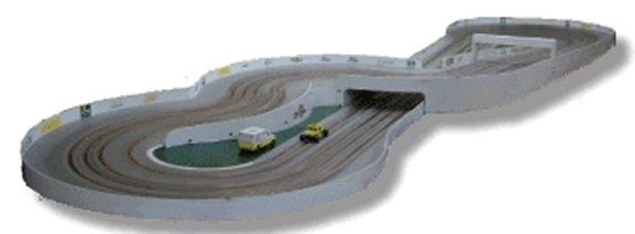
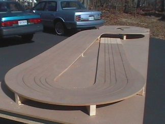
are pictures of the different building stages of my road course track. The
track is constructed of 1/2-inch MDF built on a table constructed of 2x4's
and topped with 1/2-inch MDF. The table surface measures 4 feet x 16 feet.
I put the table on casters so that it may be moved if necessary. The track
surface was cut from two 4x8 sheets of MDF with a small piece (the light colored
piece under the overpass) linking the two big sections together.
I designed the
track on the computer using Turbo Cad. This eliminated a lot of trial and
error fitting and mistakes. I could determine each turn radius, elevations,
and bank construction.

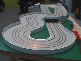
I
first routed the outside lane with a tramel and straight edge. I then used an
offset router jig I made to route the remaining slots by riding in the previous
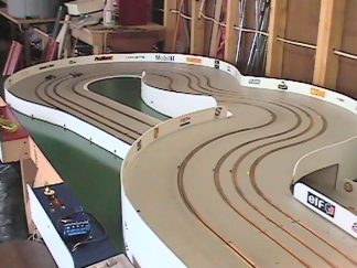
slot. The
banked turn has a 10-degree bank which allows a little more speed from the relatively
short track. But at the same time, you still have to "drive" through
the turn. The other end of the track has a flat turn going into the S's. I have
6-inch aprons on most of the turns to leave plenty of room for the larger cars.
The
slots are 1/8-inch wide, 5/16-inch deep, and I used 1.5 mil 3/16-inch wide copper
tape for power. The MDF is painted with three coats of light grey satin latex
garage floor enamel. A 12-volt battery powers the track through two power taps.
The track walls are
made from 1/8-inch tile board with the tile side facing the track. The back
side is painted white.
I
tried to cover as little of the track as possible with the overpass by crossing
at a 90-degree angle. The clearance is 3 1/2 inches to allow my taller cars
to pass through.
Each
of the four drivers stations is
wired for alligator clip connections. Each panel has brakes,
a reverse switch, a kill switch, and a power indicator light.
The reverse
switch lets you basically run a different track in the opposite direction. The
kill switch eliminates hectic marshalling problems.
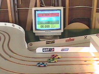
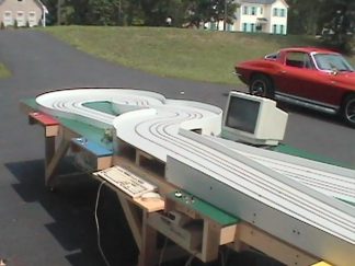
I
am using Lap Timer 2000 for a
timing system. I built the light bar over the track to trigger the Radio Shack
infrared photo transistors in the track as the cars pass over. I am using this
system with an old computer I had sitting around. The system works flawlessly!
The whole system cost less than $20 (not counting the computer) and very simple
to construct. I
tried using LED's in the light bar with little success. I switched to two 25-watt
(to cut down on heat) long bulbs. They produce plenty of light to trigger photo
transistors. The light bar itself is constructed of MDF and 1/4-inch plywood.
The supports are notched to just slide over the walls on either side.
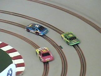
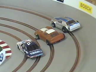
You'll
notice that my lane spacings are not the same for all 4 lanes. Three of the
lanes are spaced 2-inches apart for HO scale cars using Slide Guides.
I can use the
two outside lanes and center lane, spaced 4-inches apart, for 1/32 and 1/24
cars. This way I can run all scales of cars and still have door-banging action.
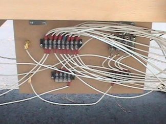
Track
wiring is attached to a hinged panel that swings down from under the track for
access. Each lane is fused with a 5-amp fuse. The 12-volt battery is alligator-clipped
to the two brass screws on the left.
The
computer is mounted under the track in the center. The wall panel over the keyboard
is removeable to have access to the power taps and the infrared photo transistors.
The name says it
all! The track is short but a blast to drive. Thanks for taking the time to
view my efforts!