| Architecture and Assembly Language Programming for the H8/3292 | |||||||||||||||||
| There are 8 16-bit registers that can
also be configured as 16 8-bit registers. There are 57 basic
instructions including multiply, divide, and bit-manipulation
instructions. There is a maximum of 64-kbytes address
space. The maximum clock rates are 16MHz at 5Volts, 12MHz at
4Volts, or 10MHz at 3Volts.
There are eight addressing modes:
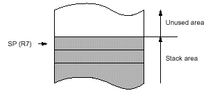
The following is the register layout of the H8/3292, click on the image for an even larger version of it. As you can see, the registers are referred to as R0 through R7. Each has a low and a high part. This is very similar to the Intel architecture found in modern desktop computers. However, one large difference is the fact that the R7 register is also the Stack Pointer. This is slightly different from the Intel system. Also, there are more registers, 8 in the H8, but on 4 in the Intel chips. It should also be noted that the H8 is more RISC like in design than the average Intel chip. The Stack Pointer can be referred to as either R7, or SP. The Stack Pointer in this architecture points to the top of the stack area. That is, the last item that was put on the stack, and not the first area of free space. See image below:
Initial Register Values When the CPU is reset, the program counter(PC) is loaded from the vector table and the interrupt mask bit (I) in the Condition Code Register(CCR) is set to 1. None of the other registers or parts of the CCR are initialized. It is important to note that this includes the Stack Pointer(SP). Therefore, the SP and the CCR should both be initialized by software, by the first instruction executed after a reset. |
|||||||||||||||||
| Register Data Formats | |||||||||||||||||
 |
|||||||||||||||||
| Back To Main Research Page | |||||||||||||||||
| Back To My Homepage |

