|
LIGHTWEIGHT DT/SHUTOFF
By
Len Sherman
The frequent loss of the Harbor Freight ARFs suggested that a motor shutoff
system would help in reducing flyaways. Because the power to weight ratio of
these models is marginal to say the least, it is necessary to keep the
weight as low as possible and still have a reliable system. Here is one that
has worked well for me.
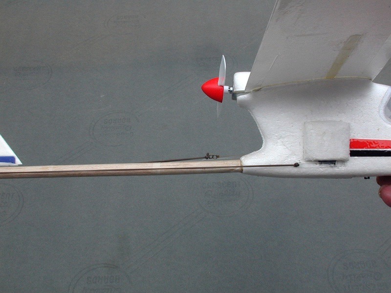
The first task is to reduce the weight wherever possible. The installed
tailboom is very heavy, so replacing it with a much lighter one will more
than compensate for the modifications done on the tail. Cut off the tailboom
about one inch aft of the fuselage. Replace this with a 1/32" sheet balsa
tube which is made by soaking the sheet overnight and then forming it around
a 1/4" diameter rod or tube. Wrap it with gauze and let it dry overnight.
Slip it off the rod and glue the seam with cyo. Sand the original part of
the tailboom protruding from the fuselage until the new tailboom will slide
on easily. Glue in place with the seam on the bottom. Cut the boom to a
length that is equal to the posirion of the original horizontal tail
trailing edge. Add a short balsa plug to the aft end of the tube. Cover with
tissue and dope.
Install the aluminum tubes as shown in the photos. These tube will carry the
DT and shut off lines.
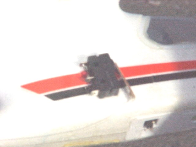
Before mounting the micro switch, drill a small hole in the leaf near the
free end. This will be for attaching the cutoff line. Cut a hole about an
inch square in the left side of the fuselage 1 1/4" forward of the tail boom
exit and 1/2" above the bottom of the fuselage. Save the plug which will be
glued back in later. Cut the yellow wire leading to the motor about 2" from
the motor. The ends of the yellow wire will go through the right side of thefuselage and be soldered to the micro switch terminals. Drill two holes in
the right side of the fuselage using the stretched wires as a guide. This
will automatically locate the position the micro switch. The orientation of
the switch is leaf down and forward. Note that there are three terminals on
the switch-use the two that closes the circuit when the leaf is depressed.In other words solder the wires to the correct two. Glue the switch in place
and make and attach a cover to protect it. Now glue the plug back in that
you previously saved.
The timer is the smallest Badge that was made at the time purchased several
years ago. Make a 1/64" thick plywood plate with a hole that matches the
bulge in the bottom of the timer and glue to the fuselage as shown in the
photos. I inset the plate in the side of the fuselage as shown just as I did
with the micro switch. Drill a couple of tiny holes for screws for the bolts
to hold the timer to the plywood.
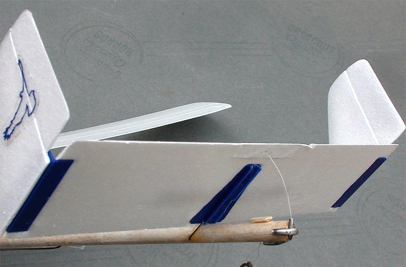
For the horizontal tail hinge, remove the plastic tail platform from the old
tail boom. Drill a small hole through the front flanges to accept an .020"
piece of wire. This will be for the hinge pin of the pop-up stab. Bend a
piece of .020" wire into a u-shape with the bottom of the "u" through the
drilled holes. Strip off the protective cover on the lower surface of the
stab and install the tail platform. Reinforce the trailing edge where the
release line will pass through. I used a small strip of Tyvek glued on with
white glue.
Rigging: Use 10#-20# monofilament for the loops on the ends of the lines and
for the portion that runs through the tubing at the end of the boom. The
rubber that I used was .050" wide strip. The cutoff rubber had a finished
length of 4.5" and the DT was 4.0". These lengths give a cutoff time of
about 10 seconds when the timer has rotated 180 degrees and DT time of about
1.5 minutes when rotated 540 degrees. To get this, wind the timer one
complete turn with the DT line hooked up and then add the cutoff line and
turn another half turn. For longer power flights, wind the timer farther.
Using this system, one can get 6 or 8 flights with a half-charge on the
system.
|
|