Robotics Research
I finally ordered some parts from Digi-Key in order to begin the prototyping process of the electronics and software. To get the electronics started, I decided to mount a solderless breadboard on one of the robots, hence "BreadBot." The idea of BreadBot is to establish the design for a universal 'base-board' which will form the basis of each robot's electronics. Once I am satisfied with the design developed using BreadBot, I will get PCBs made for all six robots.
Because the same base-board will be used for each robot, several core functions will be built into the board itself while other specialized, peripheral functions will be accomplished using a unique daughterboard. The core functions will include the power supply, motor drivers, motor feedback and control circuitry, and wireless communication.
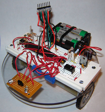
Above is BreadBot in all its glory. I know it looks like a rat's nest, but it gets the job done. In the photo, BreadBot is wired up with a modified version of the power supply mentioned above. It also has motor feedback and control circuitry and an infrared obstacle detector wired up.
My latest software development is a full proportional integral derivative (PID) motor speed controller. While it still needs some work, I am very pleased with the results so far. I used the Ziegler-Nichols tuning method to come up with constants for the PID equation and couldn't be happier with the outcome. Upon testing BreadBot with the tuned PID control software, I observed very little speed variation despite changes in terrain and even small obstacles. I would definitely recommend the Ziegler-Nichols method for efficiently tuning a PID control loop as it requires no knowledge of the target system's dynamics.
Originally, I planned on tuning the PID loop using the LCD screen from the LCD Demo. However, I recently got my BlueSMiRF Bluetooth modems in the mail and decided I'd try to get a wireless debugging interface set up. Interfacing with the microcontroller was painless; I just attached Tx to Rx and Rx to Tx. I left the CTS and RTS pins on the BlueSMiRF tied together because I didn't need to use hardware flow control in this implementation. I then established a virtual Bluetooth serial port between my PC and the BlueSMiRF and opened up HyperTerminal. From there, it was all software.
My PID control loop was running ten times a second, so I decided the tuning code would run out of the same loop in the software. I just added a snippet of code at the end of the PID loop to send the current motor speed to the BlueSMiRF so I could read it off of HyperTerminal. To apply the Ziegler-Nichols method, I cut out all of the integral and derivative code leaving just proportional control. I then ran the code in BreadBot, adjusting the gain (proportional constant, Kprop) until a disturbance in the loop resulted in oscillation of the process variable (in this case motor speed) with sustained amplitude. After finding the gain and period of this oscillation, the ultimate gain and ultimate period respectively, I just plugged the values into the Ziegler-Nichols equations to get the constants, and then plugged the constants back into the original PID loop. More information on the Ziegler-Nichols method, including equations, can be found here.
The C source code for my PID controller is available here. Although it resembles pseudocode, this is how simply code is actually written using CodeWarrior. The periodic interrupt and encoder interrupts are implemented in CodeWarrior using modules called "beans" that take care of all the lower-level programming. This software greatly simplifies the development process and I would recommend giving it a try if you haven't already.