 |
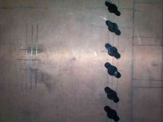
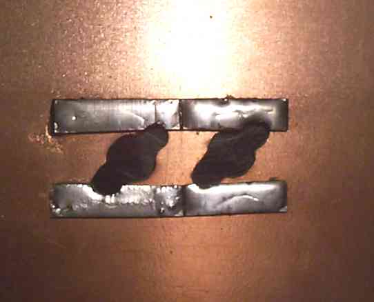
| Next will be the tabs that the xfmrs will rest upon. These strips will require a little more involvement. First, the cut from the excess copper was two strips 6" long x 3/8" wide. Once cut, the strips were laid across the xsistor holes flanged edge. Once laid, they were secured in place by using Super Glue. Yes, Super Glue. With the fiberglass side of the board roughed by emory cloth, the glue was applied to the fiberglass side and then pressed onto the surface of the copper board. Once the glue dries, the tabs will be secure for some time to come. They won't come loose. Then, the flanged edge was cut using the Dremel tool to the shape of the xsistor edges. Notice the form fitting of the edges. This makes for a clean look. Also, it hides the slip I had in the initial board prep. |
|
 |
 |
| 19 20 21 |
 |
 |
 |
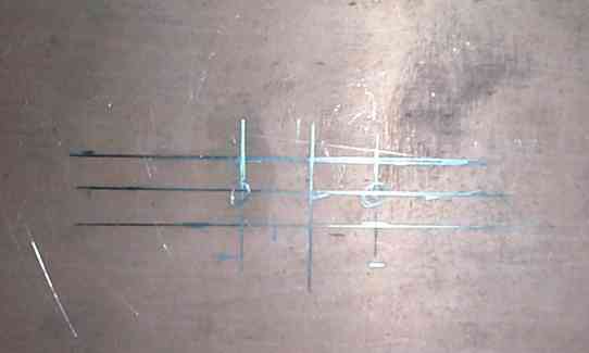
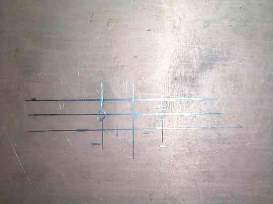
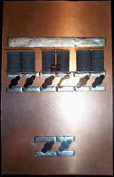
| Alignment of the driver section must compensate for the input divider. The pencil etching on the copper sheet on the above pictures show where the xsistors will be positioned. This crude method allows for flexibility in xsistor placement. The input divider will be place directly between the two sections. The overall size of heatsink allows for this positioning. A different size heatsink will allow for other parts placement. |
 |
 |
| The board has been cleaned and shined. It looks a whole lot better. To preserve the look of the board it is recommended that you treat the surface with some type of protectant. I find that a very light coating of a spay on shellac works just fine. (I use Zinsser's Bulls Eye Shellac Sealer & Finish clear spray) I repeat, a very light coat. If not treated, the board will develop a patina over time. Copper does oxidize. The Board is now finished. The rest of the parts will be place on the board's surface. Hence the term, Surface Mount. |
| 14 15 16 17 18 |
| That didn't take long to do. Now it is time to ready the board for the various parts that are to be place upon it. This stage of the project won't take long either. The B+ power strip and mounting tabs for the input and output xfmrs will be applied next. These will include the driver and the final sections. |
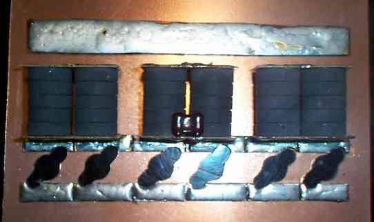
| The easiest strip to do is the B+. This strip of copper board was cut from some leftovers from another project. The actual cut is 6" long x 5/8" wide. This dimension was chosen because there will be an ample amounts of current draw across this strip. This size is acceptable to handle the amount of current that the project will call for. |
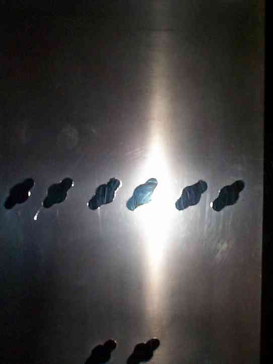
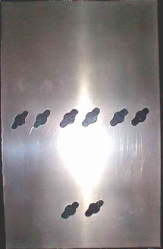
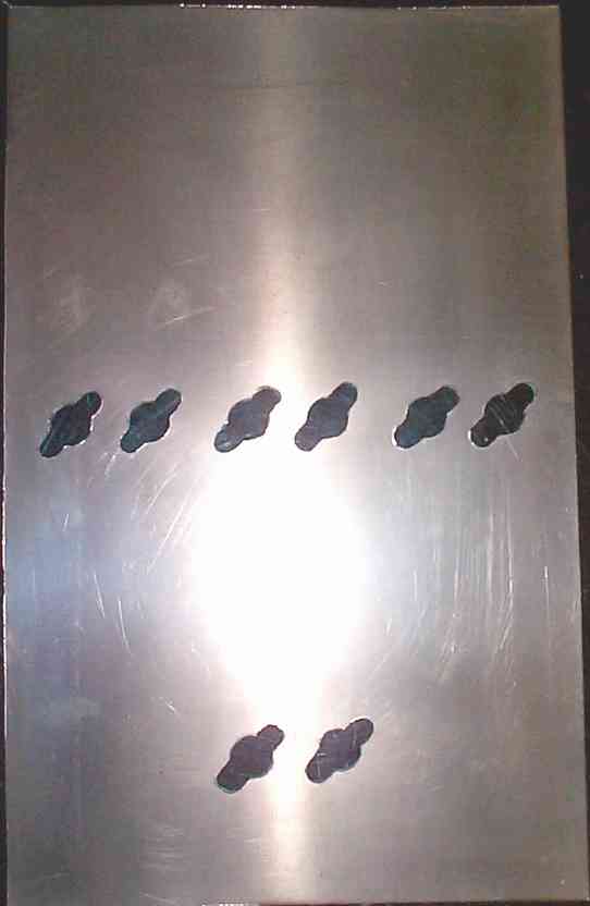
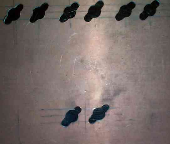
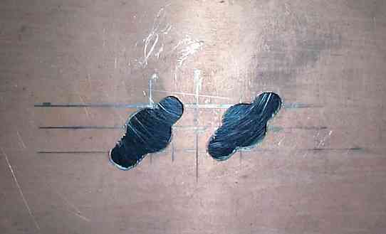
| With the tabs securely in place, the placement of the output xfmrs were laid. These were soldered to the the tabs. Spacing for the xfmrs were approxiamately one inch. With one inch divider spaces to separate each side of the xfmr. The details in Picture 24 will show the cuts made for the spaces. The same was done for the driver section. |
| Hello 2 Grand! |
 |
 |
 |
| 22 |
| 23 24 25 |
| I plan to finish the project. I have been real busy. Forgive the delay. The process will begin again in about 2-3 weeks. To all those who sent me emails, I thank you for looking. Yes, the project will resume. |