Stereography with Lightwave 3D
by Tony Alderson
Introduction
The inclusion of a stereo camera in Lightwave 3D v5.6 is a welcome addition. Indeed, with this feature, one can
now say Lightwave is finally 3-D! But the initial implementation is simple, and the documentation incomplete.
Rather than solve the issue of stereoscopy in LW, it raises the question of how stereo should be done. In the hope
of encouraging more three-dimensional imaging among the friends of Newtek, and getting some more useful stereo
plug-ins in the next version, I offer this reflection on stereo rendering. (Actually, most of this article will be
of use to digital stereographers, regardless of software.)
While the practice of stereography is really not that difficult, the best techniques are not obvious. Fortunately,
we humans have over a century and a half of experience in the art, so others have already made the mistakes for
us. Unfortunately, since stereo display is somewhat difficult, stereoscopy has always been a peripheral medium,
and popular misconceptions abound. But a little research, a little experimentation, and a little thought should
help us to a resolution.
The Stereoscopic Rendering option in the camera panel allows one to set a value for the "Eye Separation", and
saves the resulting left and right eye images to the same directory, with a "L" or "R" inserted into the name. The
default is 60 mm, although the average adult human interocular is closer to 65 mm. (Although, as we shall see, it
is not a bad idea to be conservative on this.)
The manual addendum offers the hint to:
"Use a null object as a Camera target and place it at the point where you want eyes to converge."
Besides being pretty vague, and of confusing terminology, this is not good advice.
To understand why, let's first examine a stereograph, and then reason back to making such an image. For
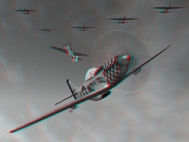
illustration, we will use anaglyphs. Not only should this method be universally accessible, but viewing the
anaglyph WITHOUT the glasses helps reveal a number of important factors. For all the pictures on this page, the
RED filter should be over your LEFT eye, and the BLUE (or cyan) filter over your RIGHT.
Elements of the Stereo Image

The images of the stereo pair should be identical in every way except for the differences in horizontal parallax,
resulting from the horizontal offset of the left and right lenses. If you examine the image carefully, with the
glasses off, you will see the homologous points are perfectly aligned vertically. This is important, as our eyes
do not rotate up and down independently.
With your glasses on, notice how the border becomes a window for the stereo image. The sky extends behind this
window, and the P51 floats out of the window. Taking the glasses off, one can see the color fringes for elements
IN the screen go one way, and the fringes for the elements OFF the screen go the other. The fringes for the tail of
the Mustang coincide, and this point appears at the plane of the screen. The coinciding plane is also called the
plane of zero parallax, and sometimes the plane of convergence (althought I do not like this last term, for reasons
I'll explain later). Elements in the screen, for mathematical convenience, are said to have positive parallax, and
elements off the screen have negative parallax. The stereo image is not just framed, but contained by the stereo
window. It is important to realize the stereo window is not necessarily the physical screen, but is the frame of
reference for the three dimensional image, and has a depth position of its own. (Only stereos of very wide angle,
such as immersive VR or IMAX 3D can be said to be free of the stereo window.)
Geometry of Stereo Photography
So how do we generate the stereo image? We can set up the scene in the usual way, considering the camera as the
viewfinder of our stereo camera. If we enter an appropriate separation value, but with no camera target, the left
and right images will be generated with parallel axes; the lenses will be converged at infinity. (Please note that
in the diagrams below the camera separation is exaggerated for clarity.)
 |  |
| Parallel cameras |
With the lenses converged at infinity, infinity will appear at the plane of the screen, and everything else will
be coming off the screen. This may put excessive screen parallax on the foreground objects, and make the image
difficult to view. (Note the "ghosting," or double images apparent around the P51.) None of the available screen
space (the space inside the monitor) is used, only the theater space (the space off the screen).
 |  |
| Toed-in cameras |
One way to solve this problem is to toe-in the camera lenses; that is, we set a null object at the plane we wish
to appear at the screen, and target the camera to it. But if you examine the image carefully, you will notice that
this cure creates another problem. (You may want to jump to the full-size image, rather than the thumbnail on this
page. I have made this a monochromatic anaglyph so the fringes will be easier to see.) If you look at the corners
of the image, you will see that homologous points are no longer aligned vertically. This is because toe-in
introduces opposing keystone distortions in the stereo pair. Now it's true that humans can stand a small amount of
vertical disparity, but not very much, and vertical misalignments are one of the major sources of eyestrain. You
know, those 3-D headaches you hear about?
Keystoning is an artifact of perspective
A better solution is to keep the lenses parallel, but translate the images horizontally in relation to one
another, pushing the stereo image into the screen. We can thus set the plane of zero parallax to any plane on the Z
axis.

We trade image width for zero vertical disparity
But of course this creates another problem: we have to sacrifice some image width. Note the bands on either side
that result from the translation. These bands need to be cropped or masked off. If a narrower image is not
acceptable, we can render to a wider size, and then crop down to the proper width after translation. (This is
necessary to fill a TV screen, for example.) The anaglyph that started this page was rendered with parallel
lenses, translated and cropped.

Another way of looking at translation: Using Limited Region
An even better solution is to design our stereo camera to do all this for us. The famous Stereo Realist camera,
for example, had a built-in stereo window by insetting the lenses slightly in relation to the film apertures. That
is, the film apertures were spaced about 71.25 mm apart, while the lenses were spaced about 70 mm. It would be cool
if Lightwave could allow us to vary the lens inset, for varying window placements while keeping the lenses
parallel. Essentially this can be done using the limited region feature, but since that is strictly mouse-driven,
with only percentage feedback, it is clumsy to the point of unusability for the stereoscopic Lightwaver. But it
might be adaptable with a plug-in. So I inevitably take the Lightwave pair out to some other program to process for
display.
Next Page
Back to 3D Home