 - The KC5LDO Vertical Antenna -
Antenna for Field Day or Everyday
Here's a simple yet rugged six band 1/4 wave vertical antenna system perfect for
field day or home use. The only tool required for assembly is a screwdriver which
is used to adjust the vertical element. The rest is assembled using wingnuts and
carriage bolts. Assembly can be done by one person including sixteen radials in
about thirty minutes.

The majority of the project was built with aluminum materials salvaged from the
scrape pile at work. Aluminum makes the antenna light weight and easy to transport.
|
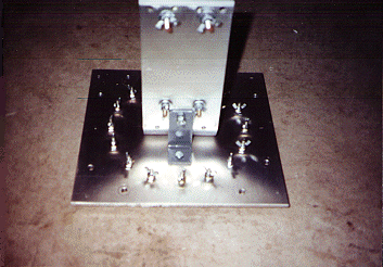
Antenna Base Plate
|
 |
The dimensions given are for my antenna and slight variances should not matter.
I like to be creative with the materials I have on hand.
The base is 1/4 inch thick aluminum plate 10 1/4 by 11 1/4 inches. I used a dinner plate
to mark a circle on the base plate. I then drilled sixteen holes around the circle to
accommodate one inch long 8/32 screws and nuts. These use wing nuts to attach the
radials. Use a minimum of four radials per band. I used eight radials for 20m., four for
10m. and four for 15m. Of course you could use sixteen radials on one band or even
more if desired.
|
Element and Legs for Base Plate
|
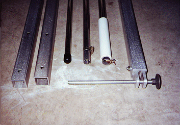 |
The four aluminum legs that  attach to the base are 1 1/2 in. square tubing, 54 in. long.
They are attached to the base with 5/16 in. carriage bolts and wing nuts. Hole spacing
is six inches. The leveling system at the end of each leg is quite simple and allows the
radiating element to be kept vertical. I used 7/16 inch all thread rod which comes in
three foot sections from most hardware stores. This was cut into four pieces.
For ground contact, a large washer is attached to one of the all thread. The ends of the
legs are then tapped to accept the all thread. This will allow each leg to be adjusted
independently. NOTE OF CAUTION: Not shown in the photos are protective coverings
over the ends of these legs. Cover the ends of each rod with something such as a doorknob
or any similar, large, blunt covering. The purpose would be to prevent injury to a person
by a possible fall onto these leveling rods.
|
Base Plate with Clamps and Connector
|
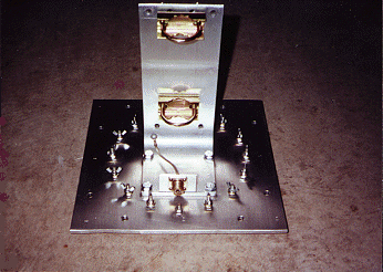 |
The vertical element is attached to the base plate by using an aluminum L bracket.
The L bracket dimensions are as follows, 1/4 inch thick, 14 inches long by 4 inches wide.
This was bent 90 degrees, five inches from one end using a hydraulic press to form a L.
Four bolts attach it to the base. Two 2 3/4 inch antenna mast clamps purchased from
Radio Shack are used to secure the vertical element to the L bracket. The clamps also
use wing nuts. A small aluminum L bracket is used to mount the SO239 connector.
This bracket should have a good ground connection to the base. I used 1/8 inch wide
wire braid to connect the center of the SO239 to the vertical element.
|
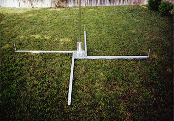
Base Plate with Legs and Element
|
 |
The vertical element is made using three 8 ft. sections of aluminum tubing. Use three
diameters that will telescope into each other. My sizes are 1 in., 7/8 in. and 3/4 inch.
These sizes are strong enough not to require guying. The two lower sections must have
one end slotted. A hack saw works great and only two slots are needed on each section.
This will allow you to adjust the antenna length to be resonant to a band of choice.
A hose clamp is then used to secure the sections together. A seven inch piece of 1 inch
I.D. PVC pipe was used for the insulator. This must be slotted along its length to allow
it to squeeze tightly around the tubing.
A 6/32 screw and nut was installed at the bottom of the tubing for connection to the
SO239. A wing nut was also used here.

To determine the proper element and radial length use the following formula:

             L=234/freq.

L is the length of the element or radial and freq. is the frequency in MHz.
|
Antenna Assembled
|
 |
The antenna project took about fifteen hours to build and cash outlay was about $30.
Most of this was spent on aluminum tubing. Square tubing is not cheap and angle iron
could be substituted for the legs. The wire for my radials came from a surplus wiring
harness that was given to me. It looks to be about 20 ga.
As an after thought, I put eyelets on the ends of the radials and made L pieces out of
coat hanger wire. These are pushed into the ground and the radials kept in a line.
I found that using the formula to calculate element length will get your SWR very
close to perfect. Near by objects and ground conductivity may make it necessary to
vary your length a few inches either way. I had to make adjustments 1/4 in. at a time.
The tubing diameters used give an acceptable band width on bands 20 thur 6 meters.
|
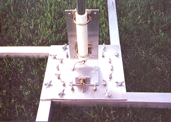
Antenna assembled with radials at Field Day 2003
|
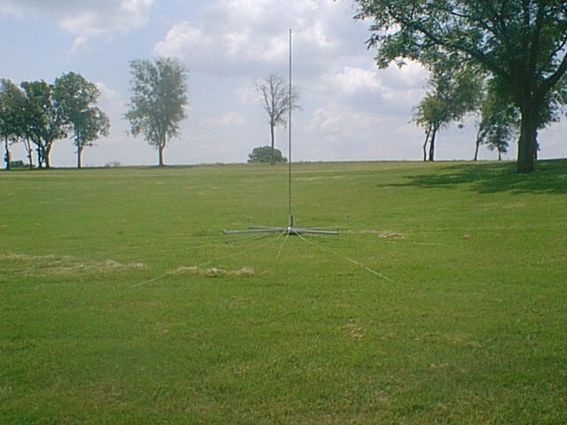 |
In the future I may experiment with a vertical element using traps.
Till then, 73 and good DX! James Tobola - KC5LDO
Build It Yourself
Tuner - Power Generator - Receiver - Antenna
Articles written by James Tobola - KC5LDO
and reproduction, publication, or duplication of this article, or any part thereof, in any manner is prohibited without the express written permission of the author.
©2001-2007

Sign Guestbook
 View Guestbook
Webpage designed and updated by Larry Merritt - KC5BFM
©2000-2009