| Manufacturer: | SICK, Inc. 6900 West 110th Street Bloomington, MN 55438 |
| Model: | OMD 41 |
| Number of COM Locations: | 1 |
| COM Material of Construction: | Carbon Steel |
| COM Ambient Temperature Range: | -4 °F to 131 °F |
| Relative Moisture: | 95% |
| Signal Output: | 4 - 20 mA |
| Operating System: | Dedicated COM Software |
| Manufacturer: | Auburn Systems, LLC 8 Electronics Avenue Danvers, MA 01923 |
| Model: | TribolinkTM |
| Number of Probe Locations: | 4 |
| Number of sensors/location: | 2 |
| Detector Material of Construction: | 316 Stainless Steel |
| Probe Temperature Range: | -40 °F to 450 °F |
| Input/Output Interface: | PC |
| Operating System Platform: | Windows 98 |

| Particulate | 10% | 25% | 50% | 75% | 90% |
| EAF dust, µm | <1.235 | <1.581 | <1.874 | <2.107 | <2.276 |
| Fe2O3, µm | <1.022 | <1.328 | <1.780 | <2.346 | <2.819 |
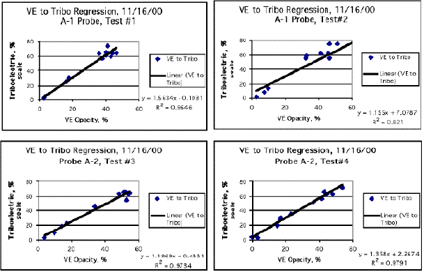

| Test #1 Probe A-1 to COM: | y = 1.878x + 22.485 R2 = 0.4054 |
| y = 24.205Ln(x) - 7.1213 R2 = 0.5782 | |
| Test #2 Probe A-1 to COM: | y = 0.7932x + 31.156 R2 = 0.3311 |
| y = 22.549Ln(x) - 13.203 R2 = 0.7056 | |
| Test #3 Probe A-2 to COM: | y = 1.4231x + 8.8582 R2 = 0.8854 |
| y = 21.934Ln(x) - 17.881 R2 = 0.9282 | |
| Test #4 Probe A-2 to COM: | y = 1.8411x + 13.226 R2 = 0.7561 |
| y = 24.875Ln(x) - 17.229 R2 = 0.9070 |


