Cases
There are several different types of case designs:
Towers: These
cases stand upright and are a good solution when many disk bays are
needed.
Mini Towers: Similar to towers, but smaller in size. These are
very common nowadays.
Desktop: Traditional design where the PC sits
horizontally often with the monitor set on top of it.
Keyboards
 |
Keyboards are input devices that
connect to the motherboard and most are of the 101/102 key variety.
Older AT keyboards used a 5 pin DIN connection while newer standards
use a 6 pin mini DIN connector that is shown to the left.
A
keyboard should never be attached or unplugged while the computer is
on as the electrostatic discharge(ESD) can damage the motherboard.
For obvious reasons liquids should not be spilled into a keyboard.
Because of their compact design, notebook computers use
smaller keyboards that typically are of the 84 key variety. Newer
versions contain Windows Keys that perform functions such as
launching Windows Explorer, minimizing windows, etc. The following
table lists the common Windows Keys commands.
|
| Key command |
Function |
| /E |
Launch Explorer |
| /F |
Launch Find Files or
Folders |
| /F1 |
Launch Help |
| /M |
Minimize all windows |
| /Tab |
Scroll through open taskbar
items |
Pointing Devices
Pointing devices
are input devices that include the mouse, trackball, light pen, joysticks
and others. The mouse is the most common of these. Newer mice called
"Wheel Mice" have a scroll wheel that allows you to scroll up and down
without having to use the scrollbars in the application.
 |
Older serial mice plugged into a DB-9
connector shown left. Newer mice are typically PS/2 compliant and
plug into a 6 pin mini DIN that are also used for keyboard
connections as discussed above.
|
Power Supplies
Intro
The power supply converts electricity
received from a wall outlet(120V AC in the U.S.A.) into DC current amounts
that are needed by the various components of the system. There are 2
different types of power supplies that correspond to 2 different types of
motherboards, and hence, case designs.
AT - This
is an older design in which the connector to the system board uses 2
6-pin(P8/P9) connections. It is important that the 2 connectors are
plugged into the system board correctly and not switched. P8 should be
plugged into P1 ont the system board and P9 should be connected to
P2.
ATX - A newer specification that uses a single 20
pin connection to the system board. These connectors are keyed to make
sure that the connector is plugged in properly.
Both models
provide 4 levels of DC voltage. ATX power supplies add an additional
voltage of +3.3V. The wires coming out of the power supply are color coded
with the black one as the ground wire.
- Yellow: +12
- Blue: -12
- Red: +5
- White: -5
- Circuitry: +/- 5 volts
- Motor: +/- 12 volts
Laptops and portables utilize an
external power supply and rechargeable battery system. Batteries were
typically nickel-cadmium, but newer techologies have introduced nickel
metal-hydride and lithium-ion batteries that provide extended life and
shorter recharge times. Lithium batteries are also used to power a
computer's CMOS ROM.
Installation/Removal
To
remove a power supply from a PC, follow these steps:
- Unplug the computer from the wall
- Disconnect all of the internal power connections(i.e. CD Rom,
Motherboard, hard disk, etc)
- Remove the 4 retaining screws
- Pull power supply out of the computer
Repeat these steps in
opposite order to install a power supply
System Boards
A system boards may
also be called a planar board, motherboard or main board. There are
various types of system boards that differ depending on the type of case
that they fit in and the type of processor that they host. The form factor
of the motherboard describes its general shape, what sorts of cases and
power supplies it can use and its physical layout. A company can make 2
motherboards that have basically the same functionality but that use a
different form factor and the only real differences will be the physical
layout of the board and the position of the components. Common form
factors include AT, Baby AT, ATX, Mini ATX, LPX, Mini LPX and NLX. The
table below contains more information:
|
Style |
Where Found |
Match to Case and Power Supply |
|
Full AT |
Very Old PCs |
Full AT, Full Tower |
|
Baby AT |
Older PCs |
All but Slimline, ATX |
|
ATX |
Newer PCs |
ATX |
|
Mini ATX |
Newer PCs |
ATX |
|
LPX |
Older Retail PCs |
Slimline |
|
Mini LPX |
Older Retail PCs |
Slimline |
|
NLX |
Newer Retail PCs |
Slimline |
NOTE:
Laptop motherboards tend to be proprietary to the model for which they are
designed. Below is a graphic that shows some of the common features of
motherboards. Note that these will vary from board to board depending on
the form factor.

ATX System Board
System Boards
typically have several components that are replaceable/upgradeable as
follows:
- Processor - Upgrading the processor is a fairly simple process. Make
sure that the new processor is supported by the motherboard.
- Memory(RAM) - Before upgrading memory, check the motherboard manual
for specifications on supported memory types and speeds.
- CMOS Battery - These batteries are designed to last 2 to 5 years.
Failure of this battery can result in an error code, however, the most
noticeable symptom is the computer's lack of ability to keep proper
time.
- BIOS ICs - Newer BIOS chips are "Flash" upgradeable using software.
Older BIOSes require replacement of the BIOS ROM chip. Before upgrading,
make sure that your processor is compatible with the BIOS and
motherboard chipset.
- Cache Memory - On some system boards, the cache memory can be
upgraded. It may be as simple as adding an IC to an open slot. Other
times, you may have to remove the existing one to upgrade.
Motherboards also contain configurable jumpers and possibly even
DIP switches(typically on older models). Jumpers use BERG pins and a small
connector that slides onto the pins to designate "on". BERG connectors are
also used to connect the front panel LEDs and switches to the board.
The back of the motherboard contains ports used for connecting
various peripherals. Peripherals are composed of input and output devices
including the mouse, keyboard, monitor, speakers, printer, etc. So what is
the difference between an input device and an output device? It is just as
the name says. The mouse and keyboard are input devices since they are
used to provide the computer with information. Output devices provide YOU
with information such as speakers, printers and the monitor. Older PC-XT
and AT board typically had a 5 pin DIN keyboard connection. The newer ATX
style uses the smaller 6 pin mini DIN connection.
Expansion
Busses:
| Bus |
Format |
Notes |
| PC-bus |
8 Bit |
Used in PC and PC-AT
models |
| ISA |
16 bit |
Runs at 8 or 8.33mhz |
| VESA |
32 bit |
Designed to address video
limitations |
| EISA |
32 bit |
Supports Plug-and-Play and Bus
mastering |
| MCA |
32 bit |
Supports PnP and Bus
mastering |
| PCI |
32 bit |
Supports PnP, Burst Mode, Bus
Mastering. Utilizes the host bridge to communicate with other types
of expansion slots. |
| AGP |
32/64 bit |
Variation of PCI designed to handle 3D
graphics better from video cards. |
Most
modern motherboards contain AGP, PCI and ISA slots.
On newer and
faster buses, a great deal of information is flowing through the channel
every second. Normally, the processor is required to control the transfer
of this information. Bus mastering involves having capable devices take
control of the bus and do the work themselves instead of utilizing the
CPU.
Plug-and-Play(PnP) - Compatible BIOSes can autodetect devices
and assign resources to them. Non PnP compatible devices are configured
first followed by PnP devices.
The IRQ(interrupt request) value is
an assigned location where the computer can expect a particular device to
interrupt it when the device sends the computer signals about its
operation. Below is a list of common IRQ settings.
|
IRQ
|
Device
|
| IRQ 0 |
System Timer |
| IRQ 1 |
Keyboard |
| IRQ 2/9 |
Video Card |
| IRQ 3 |
Open unless needed for Com 2 or
4 |
| IRQ 4 |
Com 1, Com 3 |
| IRQ 5 |
Open unless needed for LPT2 or sound
card |
| IRQ 6 |
Floppy Disk Controller |
| IRQ 7 |
LPT1(parallel port) |
| IRQ 8 |
Real time clock |
| IRQ 9/2 |
linked to IRQ 2 |
| IRQ 10 |
Open |
| IRQ 11 |
Open |
| IRQ 12 |
PS/2 Mouse |
| IRQ 13 |
Math Co-processor |
| IRQ 14 |
Hard Disk Controller |
| IRQ 15 |
Open |
Input/output(I/O)
addresses are resources used by virtually every device in a computer and
represent locations in memory that are designated for use by various
devices to exchange information between themselves and the rest of the PC.
The following is a list of common I/O settings.
1FO-1F8 - Hard
Drive Controller, 16-bit ISA
220 - Soundcard
278-27F -
LPT2
2F8-2FF - COM2
320-32F - Hard Drive Controller, 8-bit
ISA
378-37F - LPT1
3D0-3DF - Video Adapter
3F0-3F7 - Floppy
Controller
3F8-3FF - COM1
Universal Serial Bus(USB) - A
high-speed I/O bus that supports the daisy chaining of devices(up to 127).
USB hubs are used to provide connections for multiple devices. USB
supports the addition and removal of devices while they are
on(hot-swapping). Devices are either full speed or low speed. Full speed
device cabling can be up to 16 feet 5 inches(5 meters) in length. Low
speed cabling is limited to 9 feet 10 inches(3 meters). USB supports
Isochronous transfers that can stream data such as voice or video.
BIOS
Software Layer
Model
| Layer
# |
Layer |
| 0 |
Hardware |
| 1 |
BIOS |
| 2 |
Operating System |
| 3 |
Applications | |
BIOS stands for Basic Input/Output
System and is software that manages hardware and allows the
operating system to talk to the various components. The BIOS is also
responsible for allowing you to control your computer's hardware
settings, for booting up the machine when you turn on the power or
hit the reset button and various other system functions. The term
BIOS is typically used to refer to the system BIOS, however, various
other components such as video adapters and hard drives can have
their own BIOSes hardwired to them.
|
During the rest of this section, we
will be discussing the system BIOS. The BIOS software lives on a ROM IC on
the motherboard known as a Complementary Metal Oxide Semiconductor(CMOS).
People often incorrectly refer to the BIOS setup utility as CMOS, however,
CMOS is the name of the physical location that the BIOS settings are
stored in.
Basic CMOS Settings:
- Printer Parallel Port
- Unidirectional - Single direction communication.
- Bi-directional - Two directional communication. Used by HP
printers.
- ECP(Extended Capability Port) - Same as Bi-directional but uses a
DMA to bypass processor and speed up transfer.
- EPP(Enhanced Parallel Port) - Same as bi-directional and offers an
extended control code set.
- COM/Serial Port
- Memory Address - Each COM port requires a unique memory address.
- IRQ - Every COM port requires a unique IRQ to talk to the CPU.
- COM1 = IRQ4 and 03F8
- COM2 = IRQ3 and 02F8
- Hard Drives
- Size - The Size is automatically detected by the computer.
- Primary Master/Secondary Slave
- Each hard drive has a controller built in the drive that controls
the drive.
- If two drives were on the same channel the adapter could get
confused.
- By setting one as a master it tells it which is in charge.
BIOS services are accessed using software interrupts,
which are similar to the hardware interrupts except that they are
generated inside the processor by programs instead of being generated
outside the processor by hardware devices.
BIOS routines begin
when the computer is booted and are mad up of 3 main operations. Processor
manufacturers program processors to always look in the same place in the
system BIOS ROM for the start of the BIOS boot program. This is normally
located at FFFF0h - right at the end of the system memory.
First,
the Power On Self Tests(POST) are conducted. These tests verify that the
system is operating correctly and will display an error message and/or
output a series of beeps known as beep codes depending on the BIOS
manufacturer.
Second, is initialization in which the BIOS looks
for the video card. In particular, it looks for the video card's built in
BIOS program and runs it. The BIOS then looks for other devices' ROMs to
see if any of them have BIOSes and they are executed as well.
Third, is to initiate the boot process. The BIOS looks for boot
information that is contained in file called the master boot record(MBR)
at the first sector on the disk. If it is searching a floppy disk, it
looks at the same address on the floppy disk for a volume boot sector.
Once an acceptable boot record is found the operating system is loaded
which takes over control of the computer.
For more in depth
information about the BIOS including the various setup utility settings,
read The BIOS
Companion.
Microprocessor(aka processor)
The
processor can be thought of as the brains of the system and is responsible
for executing software commands and performing calculation functions. The
following table shows the features of the various Intel processors.
Chip Characteristics
| Processor |
Speed (MHz) |
Heat Sink |
Cooling Fan |
Cache |
Sockets |
Pins |
| 8088 |
5-8 |
No |
No |
No |
DIP |
40 |
| 80286 |
6
10
12 |
No |
No |
No |
LLC
PGA
PLCC |
68 |
| 80386SX |
16 - 33 |
No |
No |
No |
PGA |
100 |
| 80386DX |
16 - 33 |
No |
No |
No |
PGA |
100 |
| 80486SX |
16 - 33 |
No |
Yes on 33 MHz |
0-256K |
PGA |
100 |
| 80486DX |
25 - 50 |
No |
Yes on 33 MHz |
0-256k |
PGA
SQFP |
168
208 |
| Pentium |
60-166 |
Yes |
Yes |
256-512k |
PGA |
296 |
| Pentium Pro |
233-266 |
Yes |
Yes |
256k-1mb |
PGA |
387 |
| Pentium II |
233-500 |
Yes |
Yes |
512k |
SEC |
242 |
| Pentium III |
450mhz-1.13ghz |
Yes |
Yes |
256-512k |
SEC/PGA |
242/370 |
- With the Pentium MMX processors, 57 multimedia specific instructions
were added to increase multimedia performance and increased the L1 cache
size to 32KB.
- The Pentium Pro added Dynamic Execution and increase L2 cache to
512KB.
- The Pentium II had integrated MMX technology and used a new Single
Edge Contact Cartridge(SEC).
- The Pentium III provided increased processor speeds, a 100mhz front
size bus speed and increased L2 cache to 512KB.
- The Celeron processors are less expensive but only have a 66mhz bus
and 128KB L2 cache.
Bus Sizes of CPU’s
| Processor |
Register |
Data Bus |
Address Bus |
| 8088 |
16-bit |
8-bit |
20-bit |
| 80286 |
16-bit |
16-bit |
24-bit |
| 80386SX |
16-bit |
16-bit |
24-bit |
| 80386DX |
32-bit |
32-bit |
32-bit |
| 80486SX |
32-bit |
32-bit |
32-bit |
| 80486DX |
32-bit |
32-bit |
32-bit |
| Pentium |
64-bit |
64-bit |
32-bit |
| Pentium
Pro |
64-bit |
64-bit |
36
bit |
| Pentium
II |
64-bit |
64-bit |
36
bit |
| Pentium
III |
64-bit |
64-bit |
36
bit |
While Intel holds the majority
of the processor market share, companies such as AMD have been producing
clones based on the X86 architecture. The table below outlines the various
socket/slot types and the processors that they support.
| Socket |
Pins |
Processor |
| Socket 4 |
237 PGA |
Pentium 60/66, Pentium
Overdrive |
| Socket 5 |
320 SPGA |
Pentium 75-133, Pentium
Overdrive |
| Socket 7 |
321 SPGA |
Pentium 75-200, Pentium
Overdrive |
| Socket 8 |
387 SPGA |
Pentium Pro |
| Slot 1 |
242 SEC/SEPP |
Pentium II, Pentium III,
Celeron |
| Slot 2 |
330 SECC-2 |
Xeon |
| Super Socket 7 |
321 SPGA |
Pentium MMX, Pentium Pro, AMD K6-2,
K6-2+, K6-3, K6-3+ |
| Socket 370 |
370 SPGA |
Celeron, Pentium III, Cyrix
III |
| Socket A |
462 SPGA |
AMD Athlon, Duron |
| Slot A |
242 Slot A |
AMD
Athlon |
Memory
There are several different
types of memory as discussed below:
ROM - ROM
stands for "read only memory" and is non-volatile. This means that the
information is stored even when the power is turned off to the computer.
An example of this would be the computer's BIOS settings that are retained
even when the computer is off. Recent advancements in EEPROM technologies
have produced Flash ROM chips that can be updated from a disk or over the
internet.
RAM - RAM stands for "random access
memory" and is volatile. Over the years a variety of memory types have
emerged including DIP, SIP, SIMM, DIMM and most recently RIMM.
| Type |
Pins |
| SIMMS |
30/72 pins |
| DIMMS |
168 pins |
| RIMMS |
184 pins |
- Static RAM(SRAM) - SRAM doesn’t have to be constantly refreshed.
Uses a lot of power. Used in old IBM XT machines and was limited to 256K
per chip.
- Dynamic RAM(DRAM) - DRAM use capacitors instead of transistors and
switches. Needs constant refresh.
- Windows RAM(WRAM) - Specific to speed up graphical windows
operations.
- Video RAM(VRAM) - Uses a dual port access system to speed up video
operations.
- Extended Data Output RAM(EDO RAM) - Has a cache on the chip and is
10-15% faster than DRAM. Requires a special motherboard.
Parity
checking adds an extra bit to the data for error detection.
High
Memory Area(HMA) is the first 64K of extended memory.
Conventional
memory is the first 640K of memory.
Upper memory is between 640K and
1024K. Used to load DOS drivers to allow applications more conventional
memory.
Extended memory is memory above 1024K.
Memory
modules should match the system bus speed and RAM speed ratings should not
be mixed when installing multiple modules. This can cause the system to
lock up or not start at all.
Virtual Memory -
Protected Mode became available with the 80286 and provided the ability to
use Virtual Memory. Virtual Memory is the ability for the computer to use
free hard drive space as extra memory.
Hard
Drives
 |
Hard drives are magnetic storage
devices that contain several discs inside called "Platters" that are
attached to a spindle motor. The number of platters varies depending
on the capacity of the drive. Platters are coated with a film of
magnetically sensitive substance that is primarily made of iron
oxide. Another important ingredient is a thin layer of cobalt alloy.
The read/write heads are responsible for reading and writing to the
platters and are attached to the head actuator which is in charge of
moving the heads around the platters. The voice coil actuator is
found in modern drives and assures that the heads are in proper
position which ensures that the appropriate tracks are read.
|
The guidance system used by the heads
is called a servo. Its job is to position the head over the correct
cylinder. The spindle motor is responsible for spinning the platters at a
rate ranging from 3600 RPM to 10000 RPM depending on the drive. Heads
typically have a coil of copper wire inside. Currents are passed through
the wires which causes the surface underneath to become magnetized,
creating 1 bit of data. The direction of the current passing through the
wiring dictates the polarity of the magnetization, which creates a 0 or a
1. To read the data, the drive's electronics detect polarity differences.
The disk's surface has tracks that are rings that are located next
to each other. Each platter has the same number of tracks, and the tracks
on the outside are larger than the tracks on the inner part of the
surface. A track location that cuts across all platters is called a
cylinder. Each cylinder is divided into sectors that are 512K in size. The
size of the sector determines the amount of data that can be written, and
the amount that will be wasted if only a few characters are in a record. A
one byte record written to a sector occupies the entire track in that
sector.
Hard drive performance is measured as follows:
- Access Time - This is a measure of the average time that it takes
the drives R/W heads to access data on the drive.
- Seek Time - This is the amount of time it takes for the drives head
to move between cylinders and land on a particular track.
- Data Transfer Rate - The megabytes per second(MBps) in which data is
transferred between the drive and the system.
There are several
different type of interfaces that can be used including IDE, EIDE and
SCSI. Each IDE interface can support up to 2 devices. IDE devices of
course each contain their own integrated controllers, and so in order to
maintain order on the channel, it is necessary to have some way of
differentiating between the two devices. This is assigning each device
either a master slave designation using jumpers on the drive, and then
having the controller address commands and data to either one or the
other. Another option is to set the jumpers to cable select. This means
that the position of the drive on the cable will determine its status. If
you are using two drives on a single channel, it is important to ensure
that they are jumpered correctly. Making both drives the master, or both
the slave, will most likely cause problems.
Hard drives can be
configured in a Redundant Array of Inexpensive Drives(RAID) configuration
that is used for a variety of purposes including data recovery and
increased read/write performance depending on the level of RAID employed.
The RAID levels are as follows:
- RAID Level 0
Disk striping will distribute data across 2-32 hard
disks. This provides the fastest read/write performance as the system
can access the data from more than one place. This level of RAID does
not provide any redundancy.
- RAID Level 1
Disk mirroring writes exact copies of data to more
than one disk. Each disk or partition of a disk will contain the exact
same data. If one hard disk fails, the data still exists on the other
disk. This level of RAID also increases disk read performance as it can
pull the data off of both disks.
- RAID Level 2
Uses Hamming error correction codes, is intended for
use with drives which do not have built-in error detection. All SCSI
drives support built-in error detection, so this level is of little use
when using SCSI drives. It is seldom used at all today since ECC is
embedded in almost all modern disk drives.
- RAID Level 3
Stripes data at a byte level across several drives,
with parity stored on one drive. It is otherwise similar to level 4. It
can be used in data intensive or single-user environments which access
long sequential records to speed up data transfer. However, RAID-3 does
not allow multiple I/O operations to be overlapped and requires
synchronized-spindle drives in order to avoid performance degradation
with short records.
- RAID Level 4
Disk Striping in which the parity information is
written to 1 drive at a block level. The parity information allows
recovery from the failure of any single drive. The performance of a
level 4 array is very good for reads(the same as level 0). Writes
require that parity data be updated each time. The process offers no
advantages over RAID-5 and does not support multiple simultaneous write
operations.
- RAID Level 5
Very similar to RAID level 4, however, parity
information is written to each of the disks in the array. If one of the
disks fails, the data can be reconstructed by installing a working hard
disk. The parity information is used to reconstruct the data that was
lost.
The following procedure outlines the installation of a
hard disk.
- Disconnect the power to the computer
- Configure the appropriate master/slave settings or SCSI ID for the
drive
- Insert the drive into an available drive bay. If the drive is too
small for the bay, you will need a mounting kit
- Screw in the 4 screws - 2 on each side of the bay
- If the drive is an IDE disk, connect the IDE cable to the drive.
There should be a stripe along 1 edge of the cable. This stripe denotes
pin 1. Pin 1 on the drive is usually closest to the power connector on
the drive, however, you should consult the manufacturers documentation.
Then connect the signal cable to the motherboard ID1 or ID2 interface
making sure to note the pin 1 orientation there as well. If the drive is
a SCSI drive, a SCSI cable would be connected from the drive to a SCSI
controller card.
- Connect one of the power supply's power connectors to the drive
Once the drive has been installed it must be configured for use
in the following steps:
- CMOS configuration - Newer BIOSes autodetection features will do
this automatically. Otherwise, enter the setup utility during boot up
and configure the drive.
- Certain older drives types must be low-level formatted. Do not do
this on IDE drives!
- Partition the drive - Using the DOS utility FDISK, the drive can be
partitioned into logical drives. The disk must contain an active primary
partition that will be the C drive. An extended partition may also be
created if desired. In Windows NT, the Disk Administrator program is
used instead of FDISK. The size of the partitions can be set to a
desired size, however, note the following:
- Windows 95 Rev A(FAT16) only supported partitions up to 2GB in
size.
- Windows 95/98 OSR2(FAT32) supported drives up to 8GB.
- Even if the OS supports larger partition sizes, the BIOS must also
support logical block addressing(LBA) or the maximum partition that
you will be able to create will be either 504 or 528 MB.
- Once the disk has been partitioned, it must then be formatted. This
can be done using the DOS format utility.
Due to the magnetic
nature of hard disks, they should remain clear of magnetic fields.
Floppy Drives
Floppy drives are also a form of magnetic storage that function
similarly to hard drives. There is a spring loaded metal cover that is
moved aside during operation that exposes a mylar disk that is coated with
a ferro-magnetic substance. The drive's read/write heads access the disk
as it turns on a spindle. Older PCs used 5.25 inch disks and drives that
were able to hold 1.2mb of data. Modern 3.5 drives can hold 1.44mb of
data. Given the popularity of newer storage types such as CDROM, ZIP disks
and removable hard drives, it is not likely that further advancements to
floppy technology will be made.
The following procedure outlines
the installation of a floppy drive.
- Disconnect the power to the computer
- Insert the drive into an available floppy drive bay
- Screw in the 2 screws
- Plug the floppy cable into the drive and into the mainboard FD1
interface while noting the pin 1 orientation. Note the twist in the
cable. Connecting the floppy to the last connector on the cable will
make the drive an "A Drive" while plugging it in to the connector toward
the middle of the cable will make it a "Drive B"
- Connect one of the power supply's power connectors to the drive
CD-ROM
A beam is
emitted by the laser and directed onto a single track on the disc by a
prism/beamsplitter. As the disc rotates, the beam encounters a series of
pits and landings that determine whether the beam is reflected back into
the detector(from a landing) or scattered(from a pit). Light from the
laser beam must penetrate a thin protective layer of plastic on the disc
before striking the reflective coating that contains the pits and
landings. As the disc rotates, light reflected from landings on the disk
strikes the photo sensor producing a series of electrical pulses that are
coordinated with a timing circuit to generate a stream of 1s and 0s that
produce the binary code of information on the disc. The average storage
capacity for a CD-ROM is 680mb of data.
Newer CD-ROM drives have
the capability to record data. There are 2 main types of CD
recorders.
CD-R (Recordable) - Uses a chemical layer with a thin metal
layer(silver alloy or gold). “Burning” removes reflective parts to
simulate pits and lands and represent 1s and 0s . CD-RW (ReWritable) -
Uses phase-change material that crystallizes to write, and rewrite CDs
through a heating and cooling process.
The following procedure
outlines the installation of a CDROM drive.
- Disconnect the power to the computer
- Configure the appropriate master/slave settings or SCSI ID for the
drive
- Insert the drive into an available drive bay
- Screw in the 4 screws - 2 on each side of the bay
- If the drive is an IDE, connect the IDE cable to the drive. There
should be a stripe along 1 edge of the cable. This stripe denotes pin 1.
Pin 1 on the drive is usually closest to the power connector on the
drive, however, you should consult the manufacturers documentation. Then
connect the signal cable to the motherboard ID1 or ID2 interface making
sure to note the pin 1 orientation there as well. If the drive is a SCSI
drive, a SCSI cable would be connected from the drive to a SCSI
controller card.
- Connect one of the power supply's power connectors to the drive
Tape Drives
Tape
drives are another form of magnetic storage media that function similarly
to the other forms of magnetic media. The tape is belt driven and
read/write heads magnetize portions of the tape as it passes by them. Tape
drives are typically used for backing up and storing data. Because they
are comparatively slow, they are used to store data that does not need to
be accessed very often. Older versions of tape drives were quarter-inch
cartridges(QIC) that were approximately 6" x 4" in size. Improvements in
encoding enabled advancements in the amount of data that could be stored
on these tapes.
The newest advancements in tape technology have
brought about Digital Audio Tape(DAT) and Digital Linear Tape(DLT). DAT
tapes work in a similar fashion as a VCR tape and can store much larger
amounts of data than the QIC formats. There are several different DAT
standards as follows:
| Standard |
Compressed
capacity |
Uncompressed
capacity |
| DDS-1 |
4 GB |
2 GB |
| DDS-2 |
8 GB |
4 GB |
| DDS-3 |
24 GB |
12
GB |
Tape Drives are typically
connected to Parallel or SCSI ports.
Video Adapters
The video adapter
is the component that provides communications between the monitor and the
system board. As with everything else, there have been several different
standards over the years as follows:
| CGA |
640x200 |
| EGA |
640x350 |
| VGA |
640x480 |
| SVGA |
1024x768 |
Video Displays
A video display(AKA
Monitor) is based upon the use of an electronic screen called a cathode
ray tube or CRT. The CRT is lined with a phosphorous material that glows
when it is struck by a stream of electrons. This material is arranged into
an array of millions of tiny cells, usually called dots. At the back of
the monitor is a set of electron guns, which produce a controlled stream
of electrons. These guns start at the top of the screen and scan very
rapidly from left to right. Then, they return to the left-most position
one line down and scan again, and repeat this to cover the entire screen.
The electron guns are controlled by the video data stream coming into the
monitor from the video card which varies the intensity of the electron
beam at each position on the screen. This control of the intensity of the
electron beam at each dot is what controls the color and brightness of
each pixel on the screen. The entire screen is drawn in a fraction of a
second.
Color monitors have 3 electron guns that control the
display of red, green and blue light. The surface of the CRT is arranged
to have these dots placed adjacently in a specific pattern. There are
separate video streams for each color coming from the video card, which
allows the different colors to have different intensities at each point on
the screen. By varying the intensity of the red, green and blue streams,
the full gamut of colors is achieved.
The surface of the CRT only
glows for a small fraction of a second before beginning to fade. This
means that the monitor must redraw the picture many times per second to
avoid having the screen flicker as it begins to fade and then is renewed.
The speed of this redrawing process is called the "refresh rate".
Monitor quality depends on the resolution or "dot pitch". Dot
Pitch is a measurement of the distance between dots on the screen. The
closer together they are the better the resolution. Dot Pitch is measured
in millimeters.
 |
The monitor connects to the video
adapter via a DB-15 connector on the board. Older video standards
utilized a 9 pin connection. Some high performance monitors are
connected via a BNC connection.
Laptops once used compact
CRT based monitors, but now use Liquid Crystal Displays(LCD) because
they are much lighter and compact.
|
You should avoid exposing an LCD to
extreme light, heat and cold. Cleaning can be done with glass cleaner and
a lint-free cloth by spraying the cleaner on the cloth. Do not spray the
cleaner on the screen.
Care should be taken when working inside
monitors as they can contain electrical charges as high as 25,000 volts
which is a potentially lethal amount.
Sound
Cards
Your computer's sound card is responsible
for taking sound data from a disk(like an MP3 file) and converting it so
your computer's speakers can play it. Usually, this tweaking consists of
changing digital ones and zeros into analog waveforms your ears can
recognize.
The sound card is also responsible for doing it the
other way around. It takes external sounds such as your voice as you talk
into a microphone and converts those waveforms into ones and zeros so that
they can be stored on a disk.
Sound cards are internal cards that
are either built into the motherboard or are installed in an ISA or PCI
expansion slot. The back of the sound card contains RCA jacks for
connecting speakers and microphones.
Modems
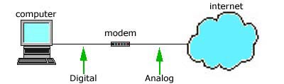
The modem is a device that converts
digital information to analog by MODulating it on the sending end and
DEModulating the analog information into digital information at the
receiving end. Modems are known as Data Circuit-Terminating Equipment(DCE)
while the computer using the modem is often referred to as Data Terminal
Equipment(DTE). Modems have different transmission modes as follows:
- Simplex - Simplex means that signals can be passed in one direction
only which means that communication only happens in one direction.
- Half Duplex - Half duplex means that signals can be passed in either
direction, but not in both simultaneously. Half-duplex modems can work
in full-duplex mode.
- Full Duplex - Full duplex means that signals can be passed in either
direction, simultaneously. Full duplex operation on a two-wire line
requires the ability to separate a receive signal from the reflection of
the transmitted signal. This is accomplished by either FDM (frequency
division multiplexing) in which the signals in the two directions occupy
different frequency bands and are separated by filtering, or by Echo
Canceling (EC). The implication of the term full-duplex is usually that
the modem can transmit and receive simultaneously at full speed. Modems
that provide a low-speed reverse channel are sometimes called
split-speed or asymmetric modems. Full duplex modems will not work on
half-duplex channels.
Modems can also be classified by their
speed which was measured by the BAUD rate. One baud is one electronic
state change per second. Since a single state change can involve more than
a single bit of data, the Bits Per Second(BPS) unit of measurement has
replaced it as a better expression of data transmission speed. Common
modem speeds are V.34 at 28.8 kbps, V.34+ at 33.6 kbps and V.90 at 56
Kbps.
Error correction is the method by which modems verify that
the information sent to them has been undamaged during the transfer.
Error-correcting modems break up information into small packets, called
frames. The sending modem attaches a checksum to each of these frames. The
receiving modem checks whether the checksum matches the information sent.
If not, the entire frame is resent. Though error correction may slow down
data transfer on noisy lines, it does provide greater reliability. As with
data compression protocols, for an error correction protocol to be used,
it must be supported by both modems in the connection.
Sometimes
one modem in a connection is capable of sending data at a faster rate than
the other can receive. Flow control allows the receiving modem to tell the
other to pause while it catches up. Flow control exists as either
software(XON/XOFF) flow control or hardware(RTS/CTS) flow control. With
software flow control, when a modem needs to tell the other to pause and
when to resume. Hardware, or RTS/CTS, flow control uses wires in the modem
cable or, in the case of internal modems, hardware in the modem. This is
faster and much more reliable than software flow control.
Most
modern modems are internal, however, they can be internal or external.
External modems are connected to the back of the system board via a RS-232
serial connection. Internal modems are installed in one of the
motherboard's PCI or ISA expansion slots depending on the modem. The modem
contains an RJ-11 connection that is used to plug in the telephone line.
Hayes Corporation developed a smart modem which accepted AT type
commands. This is now a widely accepted standard. The following is a brief
list of the AT command set.
- ATA Answer call
- ATA/ Repeat last command
- ATC Turn modems carrier signal ON (ATC1) or OFF
(ATC0)
- ATD Dial a telephone number (ATDT255-0789)
- ATE Enable (ATE1) or disable (ATE0) the echo of
characters to the screen
- ATH Hang up the phone (ATH0) or pick up the phone
(ATH1)
- ATM Turn on modem speaker (ATM1) or turn off
speaker (ATM0)
- ATO Place modem on-line
- ATP Pulse dial
- ATS Set values in modem 'S' registers
- ATT Touch tone dial
- ATZ Reset the modem
Troubleshooting
This portion of
the exam is one that is very difficult to outline in a study guide and is
where your experience is really being tested. There are far too many
different errors and solutions to be written here. We have included some
general troubleshooting information and common problems for various
components, however, this is by no means a comprehensive list. This is
where your on the job experience and work in your
home lab are
necessary.
Below is a list of useful tools for hardware
troubleshooting:
- Standard and Phillips Screwdrivers - various sizes
- IC ROM Puller - For upgrading BIOS chips
- Multimeter - A necessary tool for troubleshooting electrical issues
such as the power supply. It can also be used to do a resistance test.
When performing this test make sure that the power to the system is
unplugged.
The following table shows the readings that you
should see for various multimeter tests:
|
Test
|
Good
reading
|
| Speaker Resistance |
8 ohms |
| Fuse Resistance |
0 ohms |
| Capacitors(DC) |
5V (most of
them) |
Some components of a PC are
field replaceable and some are not. Common Field Replaceable Units(FRUs)
are below:
- Monitor
- Keyboard
- Mouse
- Floppy Drive
- CDROM
- Hard Drives
- Printer
- Video Adapter
- Sound Card
- Network Card
- Motherboard
- Power Supply
- Processor
- CMOS Battery
- RAM
Beep codes vary depending on the manufacturer of the
BIOS. Below are some of the common beep codes for an Award BIOS.
|
Beep
Code
|
Meaning
|
| 1 long |
System memory failure |
| 1 long then 2 short |
Video controller failure |
| 1 long then 3 short |
Video controller failure |
| Continuous |
Video or memory
failure |
Below are the IBM error
code families and the component that the error code relates to:
|
Error Code
Family
|
Error
Type
|
| 1xx |
System board errors |
| 2xx |
Memory (RAM) errors |
| 3xx |
Keyboard errors |
| 4xx |
Monochrome monitor errors |
| 5xx |
Color monitor errors |
| 6xx |
Game control adapter
errors |
| 7xx |
8087 or 80287 math coprocessor
errors |
| 9xx |
Parallel printer adapter
errors |
| 10xx |
Reserved for parallel printer
adapter |
| 11xx |
Asynchronous communications adapter
errors |
| 12xx |
Alternate asynchronous communications
adapter errors |
| 13xx |
Parallel printer adapter
errors |
- Lost BIOS password - Most newer motherboards have a jumper that can
be used to clear the CMOS memory. Typically this involves opening the
PC, changing the jumper to a special setting, and then booting the PC.
If the memory has been cleared, you power the PC down and put the jumper
back to its previous position
- System clock is not keeping correct time - This is typically caused
by the CMOS battery failing or running low voltage. Usually, replacing
the CMOS battery will fix this.
- System locks up consistently a few minutes after power up - This is
usually associated with a failed processor fan or general overheating.
Boot the system with the case off and see if the fan is running. If not,
the fan and likely the processor will need to be replaced.
- System appears completely dead(no visible activity during powerup) -
Check the external power cable and make sure that it is plugged into a
working outlet and securely plugged into the unit. Next, make sure that
the on/off switch is set to "On" and that the 115/230 switch is set to
the appropriate setting for your location. Verify that the internal
power connection from the power supply to the motherboard is firmly
connected. A multimeter can be used to narrow determine how far the
power is getting. Start at the outlet and work your way inside. Finally,
remove all unnecessary components from the motherboard to see if one of
them is overloading the power supply.
- Front panel lights come on and the power supply fan runs, but no
other activity is present - Try swapping out the power supply. If this
doesn't fix the problem, remove all unnecessary components from the
motherboard to see if one of them is overloading part of the power
supply.
There are 2 types of memory errors:
- Soft-memory errors - These are occasional strange behaviors that can
usually be cleared by rebooting.
- Hard-memory errors - Caused by a hardware failure related to the RAM
and will usually display a message on the screen or create a beep code.
Can be isolated by removing memory chips 1 at a time.
- System locks up while counting RAM - Usually requires that the
processor be replaced
Keyboards can have a variety of symptoms
including:
No characters appearing on the screen
6 beeps on
boot
A 301 error code
Keyboard is locked - Unlock It error
message
Keyboard Error - Keyboard Test Failure
KB/Interface Error -
Keyboard Test Failure
The most common causes for these problems
is:
Incorrect keyboard type in BIOS or Windows
Keyboard not properly
connected
Blown fuse in back of keyboard
Mice:
Cursor
skips around or gets stuck - This is usually caused by dirt and lint
inside the mouse that needs to be cleaned.
Doesn't move at all - Can be
a configuration error caused by an IRQ or address conflict, conflicting
device drivers loaded in autoexec.bat and config.sys or can be caused by a
hardware failure. If none of these are causing it, it is likely a problem
with the port on the motherboard.
Video:
- There are a variety of problems that can occur from misconfigured
drivers and settings. When possible, verify that the correct drivers are
loaded and check for IRQ and memory address conflicts
- Screen goes blank after a while - This is usually due to Power
Management settings in the BIOS
- The screen flickers - Usually caused by the refresh rate being set
too low.
- The output on the screen is garbled or looks like a bunch of moving
lines - This is most often caused by setting the resolution, color depth
or refresh rate at a higher level than the monitor supports. To correct
this, press F8 on boot and select "Safe Mode" from the menu. Set the
display settings to appropriate levels.
- No display at all and you suspect hardware - Make sure that the
monitor is plugged into a working outlet. Make sure that the contrast
and brightness settings have not been turned all the way down. Make sure
that the monitors signal cable is properly connected to the PC and that
the video card is properly seated in the slot.
Floppy Drives:
- The floppy drive will not read any disks - Check for IRQ and memory
address conflicts. Make sure that the internal power cable is connected
from the power supply to the drive. Verify that the FDD cable is
properly connected to the motherboard and the drive and that the pin 1
orientation is correct. You can also narrow down the problem by swapping
out the drive and cable one at a time to determine if the problem is
with one of them.
- The system will not boot from the floppy drive but works fine after
boot - This is usually caused either by a problem with the floppy or by
an incorrect boot sequence in the BIOS
Hard Drives:
- Make sure that the drive is properly connected and using the correct
pin 1 orientation.
- Make sure that there is only one device connected to the cable that
is configured as master.
- There are a variety of problems that can occur from misconfigured
settings. Verify that the correct drive settings are reflected in the
BIOS settings. Common error messages that can occur when these are
incorrect are "Drive Type Mismatch" and "Invalid Media Type".
- Check for IRQ and memory address conflicts in Windows.
- The system will not boot. If booting from a floppy, the drive can be
accessed from a DOS prompt - This usually indicates that the boot files
are missing or corrupt. Change directories to the A drive(with the boot
disk inserted) and type SYS C: to restore the boot files.
- From a DOS prompt, you receive a "Boot Disk Failure" or "Missing ROM
Basic Interpreter" error message when trying to view the contents of the
hard drive - Try restoring the master boot record by using the FDISK
utility as follows: FDISK /MBR.
- If all configuration settings are correct and the drive cannot be
accessed after booting with a boot disk and an "Invalid Drive" or
Invalid Drive Specification" error message appears, the disk will need
to be formatted and reconfigured.
- If the EIDE or IDE controller is dead and is hardwired to the system
board, an IDE or EIDE controller expansion card can be used without
having to replace the motherboard.
- If it is a SCSI drive, make sure that the hard drive is using a
unique SCSI ID on its chain and that proper terminiation is in place.
CD-ROMS:
- Make sure that the drive is properly connected and using the correct
pin 1 orientation.
- Make sure that there is only one device connected to the cable that
is configured as master.
- Make sure that the drive is configured correctly in the autoexec.bat
for a line similar to C:\MSCDEX.EXE /D:mscd001 /L:%CDROM% and
config.sys for one like device=aspicd.sys /D:mscd001.
- If the CD tray has become jammed and will not open, use a paperclip
or other long thin item into the tray release access hole.
- If the EIDE or IDE controller is dead and is hardwired to the system
board, an IDE or EIDE controller expansion card can be used without
having to replace the motherboard.
- If no sound is heard when playing a CD, make sure that the sound
card is properly configured and that the cable is connected between the
CD-ROM and the sound card.
- "Data error reading drive C:" or "Sector not found" error messages
consistently occur - This is typically caused by a dirty drive that
needs to be cleaned.
Modems:
- Check for I/O and IRQ conflicts
- You may need to configure a modem initialization string using the AT
Command Set.
- Check configuration settings such as disabling call waiting or
dialing a 9 first for an outside line.
- Refer to ISP instructions for advanced configuration options such as
flow control, parity, etc.
- Make sure that the correct driver is loaded for the modem.
- As with any component, make sure that it is properly seated and all
cables are correctly attached.
Preventative Maintenance
Cleaning
of outer surfaces of a computer can be done with soap and water as long as
the solution does not enter the internal parts of the computer. The
solution should be applied with a lint-free cloth. The cleaning should be
followed with an anti-static spray that can be made out of water and
fabric softener.
Internal dust can be cleaned with canned air, a
soft brush or anti-static vacuum. Anti-static vacuums are specially
grounded to prevent static discharge like regular vacuums. Dust can
contribute to overheating problems. Making sure that all expansion slot
covers are in place can reduce dust buildup. Missing covers can also
disrupt the airflow design of the case and cause overheating problems.
Additional fans can be added to help cut down on internal temperature
problems. Computer equipment should not be placed in areas of extreme
temperature or humidity.
Oxidation corrosion can slow down or even
prevent electricity from flowing through contact points. Oxidation buildup
can be removed by rubbing with an emery board or eraser. It can also be
cleaned with special cleaning solution.
Other internal components
can be cleaned with Isopropyl alcohol and lint-free swabs.
Monitors should be cleaned with a soap and water solution with the
power disconnected. Do not use household cleaning solutions as they can
damage the screen. Monitors should not be opened unless you are qualified
to work on them. Deadly voltage can be stored inside the monitor even a
year after it has been turned off.
Computer components should be
transported in antistatic foam or an anti-static bag.
Hard drives
are vacuum sealed and should never be opened except by professionals in a
"clean room".
Important data should be regularly backed up and
stored in a fire-proof safe or at a separate location for protection
against fire or theft. Windows NT/2000 Emergency Repair Disks should be
stored in a secure place where only authorized personnel can access them.
Because floppy disks are magnetic media, they should not be
exposed to magnetic fields that can be produced by TVs, monitors,
speakers, power supplies and appliances with motors. Floppy drive heads
can be cleaned with a wet or dry head cleaning disk. Keyboards can tend to
collect dust between the keys. They can be vacuumed with a small vacuum.
Mice need to occasionally have the X and Y rollers cleaned with a
lint-free swab.
Electrical spikes(measured in nanoseconds) or
surges(measured in milliseconds) can cause damage to system components or
even data loss. Surge suppressors can prevent minor variances in power and
provide a stable stream of electricity to the unit, however, they may not
always work against larger surges.
Uninterruptable Power
Supplies(UPS) provide power to the devices connected to it for a period of
time in the event of power loss or sag for long enough to gracefully
shutdown the computer and avoid data loss. Unnecessary peripherals such as
scanners and printers should not be connected to a UPS as they can
overload it.
Laser printers have several hazards that should be
noted. The laser can cause blindness, the fuser can cause burns and the
power supply can cause electrocution.
Toner cartridges, ink jet
cartridges and batteries can be recycled.
Hazardous materials come
with Material Safety Data Sheets(MSDS) that provide a variety of
information as to how the product should be handled and disposed of.
Electrostatic Discharge(ESD) can be harmful to electronic
components and cause them to fail. Low humidity, walking across carpet and
appliance motors are some of the common generators of ESD. MOS devices are
particularly sensitive to ESD and special care should be taken around
them. Below are some of the prevention methods employed to prevent damage:
- Grounding straps are connected to a technicians wrist. You can
ground the wrist strap to the earth pin on a wall socket.
- Remove all metallic jewelery.
- Antistatic mats.
- Touching the chassis of the computer while plugged into a grounded
outlet.
- Anti-static sprays can be applied to floors, computers and work
surfaces.
- A humidifier can be used to keep the humidity above 50%.
An
ESD wriststrap should never be worn when working with high voltage
equipment such as monitors.
Computer equipment should be unplugged
from the wall during electrical storms to prevent equipment damage and
injury.
Printers
Font Types:
- Bitmap - composed of dots called pixels.
- Vector - Uses mathematical forulas to plot lines. Requires less
storage space than bitmap.
- TrueType - Outline fonts for Windows only.
Feed
Mechanisms:
- Pin Feed - Paper has perforated strip on each side that contains
holes that fit onto pins that are rotated by a motor in the printer.
- Friction Feed - Typically uses rollers that press against the platen
or drum that rotate forcing the paper through the printer.
Dot Matrix - Uses a matrix of pins to imprint an image.
Uses a Ribbon. ROM programs the Fonts.
Troubleshooting:
- Smudges can be caused by the ribbon tension being too high
- Broken printhead pins can cause incomplete or missing characters.
- If the tops of characters are missing, the printhead is misaligned
with the platen and needs to be reseated or the printhead carriage may
need to be adjusted.
- If the print gets lighter on the page from left to right, the
printhead distance from the plate is uneven and will need to be
adjusted.
Ink Jet(or Bubble Jet) - No contact therefore
quiet. Works by spraying ink onto the paper in a sequential fashion.
Similar in operation to a dot matrix printer.
Troubleshooting:
- Never refill cartridges which are causing problems. The head is part
of the cartridge so replace the entire cartridge.
- If the output is disfigured or wavy, make sure that the paper
thickness level is in the correct position. If it is, then the paper
feed rollers probably need to be replaced.
Laser Printers
- Uses a Page Description Language (PDL) to print a page at a time. Main
components are:
- Cleaning Blade - This rubber blade removes excess toner off the drum
after the print process has completed.
- Photosensitive Drum - The core of the electrophotographic process.
This component should not be exposed to light.
- Primary Corona Wire - Highly negatively charged wire erases the
charge on the Photosensitive drum to make it ready for another image.
- Transfer Corona - A roller that contains a positively charged wire
to pull the toner off the photosensitive drum and place it on the page.
- Toner - Plastic Resin. Naturally Negatively charged
- Fusing Rollers - Bonds the toner particles to prevent smearing. Uses
heat to bond. A thermal fuse prevents the fuser from overheating.
Troubleshooting:
- Blank Pages - Can be caused by No Toner, Transfer Corona Failure or
HVPS Failure.
- Speckled Pages - Due to a failure in the cleaning step of the EP
Process. Or a scratch on the EP drum.
- Ghosted Images - Caused if the erasure lamp doesn’t erase all of the
image from the EP drum before the next page is printed.
- Smudged Images - The fusing process must have failed. The heating
elements in the fusing rollers may be faulty.
- Dark spots - Can indicated toner buildup at some point in the paper
path. Running blank sheets through it may clear problem.
- Jams in laser printers usually occur in the paper pickup area, the
fuser or the registration area. They can be caused by incorrect paper
settings or media types.
Electrophotographic Print Process(EP):
The process concerned with putting the image on the
page. Follows Six processes.
- Cleaning - The Drum is cleaned and electrically erased.
- Charging - The Drum is negatively charged to -5000Vdc. Done by the
Primary Corona.
- Writing - The Laser sweeps the length of the drum applying the
image. The Laser reduces the negative charge on the drum where the image
is going to be.
- Developing - The Toner is transferred to the area on the drum which
has been swept by the laser.
- Transferring - Once the image is on the drum the paper is fed
through and the transfer corona wire attracts the image from the drum to
the paper.
- Fusing - The Fusing rollers heat up and pass the paper through
bonding the toner to the paper. Uses a Non stick roller surface.
Physical Connections:
Older printers utilize a RS-232 connection that can
either be 9 or 25 pin serial port and cable. The cable should be less than
50 feet long(15.25 meters). Serial configuration requires that the port be
configured with parity type, speed, protocol and character frame must be
configured.
 |
Parallel connections utilize a DB-25
port(left) on the computer to connect to the printer. Parallel
cables should be less than 10 feet(3 meters).
|
Many newer printers also have rj-45
network connections and can be integrated with standard networks. Older
models may have coaxial network connections. Another popular connection
solution is the print server such as a Jet-Direct interface that connects
to the printers parallel port and has an RJ-45 connection at the other
end.
Scanners
Scanners are comprised of a Charge Coupled Device(CCD) array. This
array is like a series of "eyes" that read and record light intensities
and stores them in digital form. This is achieved when the scanners
internal light source passes over the image that is being scanned.
Scanners come in three basic types. The simplest type of scanner
is the hand held in which the scanning device is moved across images or
text. The scanner reads the information directly. A Page scanner works by
inserting a page into the top of the scanner which is pulled via rollers
through the scanner. The most common type of scanner is the flatbed
scanner which allows you to place a image or document on the top of its
surface, much like a photocopier. Scanner quality is measured in DPI or
dots per inch. 300 DPI is usually adequate for normal scanning, however,
modern scanners can scan at resolutions of 9600 DPI and higher. The higher
the resolution, the larger the resultant scanned file will be.
Scanners are connected to the system board via a SCSI, Parallel or
other proprietary connection method depending on the scanner model.
Basic Networking
Network models are as follows:
- Peer-to-Peer - A peer to peer network is one in which lacks a
dedicated server and every computer acts as both a client and a server.
This is a good networking solution when there are 10 or less users that
are in close proximity to each other. A peer to peer network can be a
security nightmare, because the people setting permissions for shared
resources will be computer idiots and the right people will never have
access to the right resources. Thus is only recommended in situations
where security is not an issue.
- Client/Server - This type of network is designed to support a large
Number of users and uses dedicated server/s to accomplish this. Clients
log on to the server/s in order to run applications or obtain files.
Security and permissions can be managed by 1 or more administrators
which cuts down on the aforementioned computer illiterates from medling
with things that they shouldn't be. This type of network also allows for
convenient backup services, reduces network traffic and provides a host
of other services that come with the network operating system(NOS).
- Centralized - This is also a client/server based model that is most
often seen in UNIX environments, but the clients are "dumb terminals" or
"Diskless workstations". This means that the client may not have a
floppy drive, hard disk or CDROM and all applications and processing
occur on the server/s. As you can imagine, this requires fast and
expensive server/s. Security is very high on this type of network.
Network Topologies
- Bus - This topology is older technology and essentially has each of
the computers on the network daisy-chained to each other. This type of
network is usually peer to peer and uses Thinnet(10base2) cabling. It is
configured by connecting a "T-connector" to the network adapter and then
connecting cables to the T-connectors on the computers on the right and
left. At both ends of the chain the network must be terminated with a 50
ohm impedance terminator.
ADVANTAGES: Cheap, simple to set
up.
DISADVANTAGES: Excess network traffic, a failure may affect many
users, Problems are difficult to troubleshoot.

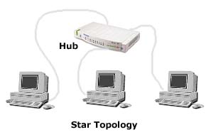
- Star - The star uses twisted pair(10baseT or 100baseT) cabling and
requires that all devices are connected to a hub.
ADVANTAGES:
centralized monitoring, failures do not affect others unless it is the
hub, easy to modify.
DISADVANTAGES: If the hub fails then everything
connected to it is down.
- Ring - The ring topology looks the same as the star, except that it
uses special hubs and ethernet adapters. The Ring topology is used with
Token Ring networks which are not very common.
ADVANTAGES: Equal
access.
DISADVANTAGES: Difficult to troubleshoot, network changes
affect many users, failure affects many users.
- Mesh - Mesh topologies are combinations of the above and are common
on very large networks. For example, a star bus network has hubs
connected in a row(like a bus network) and has computers connected to
each hub.
Cabling
TYPES
| Cable Type |
Also Known As |
Connector |
Maximum Length |
| 10Base5 |
RG-8 or RG-11, Thicknet coax |
AUI/DIX |
500 meters(1640 ft) |
| 10Base2 |
RG-58, thinnet coax |
BNC connector |
185 meters(607 ft) |
| 10BaseT |
Cat 3, 4, 5 twisted pair |
RJ-45 |
100 meters(328 ft) |
| 100BaseT |
Cat 5 twisted pair |
RJ-45 |
100 meters(328 ft) |
| 10baseFL |
Fiber Optic |
Fiber Optic connector |
2 Kilometers(6562
feet) |
Speed
| Cable Type |
Transmission Speed |
| Thicknet |
10mbps |
| Thinnet |
10 mbps |
| cat 2 twisted pair |
4 mbps |
| cat 3 twisted pair |
10 mbps |
| cat 4 twisted pair |
16 mbps |
| cat 5 twisted pair |
100 mbps |
| Fiber Optic |
100 mbps - 1
gbps |
Misc Cable
Info
- Shielded twisted pair(STP) differs from UTP in that it has a foil
jacket that helps prevent crosstalk. Crosstalk is overflow from an
adjacent wire.
- Plenum grade cabling is required if the cabling will be run between
the ceiling and the next floor(this is called the plenum). Plenum grade
is resistant to fire and does not emit poisonous gasses when burned.
- Thicknet is often used as a backbone. A transceiver with a vampire
tap penetrates the core of the cable. From the transceiver a DB-15
connector plugs into the AUI port on a given device.
- Fiber Optic cabling has an built in security as you can't intercept
data as you can with other cable mediums.
- Baseband= Digital, single frequency, bidirectional communications
and uses a repeater to regenerate signals.
- Broadband= Analog, multiple frequencies, unidirectional
communications, uses amplifiers to boost signals.
- A Time Domain Reflectometer(TDR) can be used to find opens and
shorts in cables.
Access
Methods
- CSMA/CD - This stands for "carrier-sense multiple access with
collision detection" and is the method used on ethernet networks whereby
all computers on the network check the cable for traffic before
attempting to transmit a packet. If more than 1 transmits at the same
time then there will be a collision and both computers will wait a
random amount of time and retransmit.
- CSMA/CA - Stands for "carrier-sense multiple access with collision
avoidance". This access method prevents collisions by having computers
broadcast an intent to send a packet. This is the access method used by
Localtalk and is sometimes described as "chatty". This broadcasting of
intent to send can cause excess network traffic and slow things down.
- Token Passing - Token passing is the access method used by token
ring networks. With this method, a packet called a token is passed
around the network. A computer that wishes to transmit must wait until
it can take control of the token, allowing only one computer to transmit
at a time. This is sort of like the "conch" in Lord of the Flies. Piggy
had all of this crap that he wanted to whine about all of the time, but
could only do so if he possessed the conch.
- Demand Priority - This access method is used with 100VG-AnyLAN
networks. The repeaters, bridges, routers or hubs search the network for
requests that are waiting to be sent. If 2 or more requests are received
by the network hardware at once, the data with the highest priority is
sent. Priority for different data types can be controlled by the
administrator. A real advantage is that computers can receive and
transmit at the same time with this access method.
Frame Types
| 802.1 |
Internetworking |
| 802.2 |
Logical link control - LLC adds header
information that identifies the upper layer protocols sending the
frame. |
| 802.3 |
Ethernet - Media Access Control (MAC)
sub-layer uses Carrier Sense Multiple Access with Collision
Detection(CSMA/CD) |
| 802.4 |
Token bus LAN |
| 802.5 |
Token Ring BUS |
| 802.6 |
Metropolitan Area network
(MAN) |
| 802.7 |
Broadband |
| 802.8 |
Fiber optic |
| 802.9 |
Integrated voice/Data |
| 802.10 |
Network Security |
| 802.11 |
Wireless Networks |
| 802.12 |
Demand Priority. Like 100VG-Any
LAN |
Network Cards
and Protocols
- Like other expansion cards, network cards require that the
appropriate driver is loaded to function properly.
- If an network card will not function it may be due to an IRQ or
memory conflict. Typical settings for these are:
- IRQ - 5
- Port Address - 300h
- Base Memory - D8000h
- ISA network cards are not PnP compatible and have to be manually
configured.
- Network communication uses a set of "rules" called protocols. Common
protocols on modern networks are IPX/SPX and TCP/IP. These protocols
regulate how packets are packaged and sent across a network. If devices
do not have the same protocols configured and there is no "middleman" to
translate, they will not be able to communicate with each other.
PCMCIA
The PCMCIA bus was developed for smaller computing devices and is
hot-swappable. There are 3 types of PCMCIA cards:
- Type I - 3.3mm thick and used as memory expansion units.
- Type II - 5mm thick and most expansion functions except removable
hard drives. Type I cards will work in them.
- Type III - 10.5mm thick and used mainly for removable drives. Type I
and II cards will work in them.
|