Instructions on How to Install
the Blitz Dual Turbo Timer
By Harry Yamashita
SpdDemon13@aol.com
Due to many of the TwinTurbo.net members' requests for instructions
on the installation of the Blitz Dual Turbo Timer, I have decided to up
this DIY up on the web.
Typical locations for mounting a Blitz Dual Turbo Timer (hereon
referred to as BDTT) are on the panel under the steering column, on the
steering column, in the stock 300ZX clock location, and in one of the DIN
stereo openings. I will refer to the installation of the stock clock location
for now. Here's a pic of some location ideas (obviously some pics are not
of the Blitz unit but you get the idea... :)
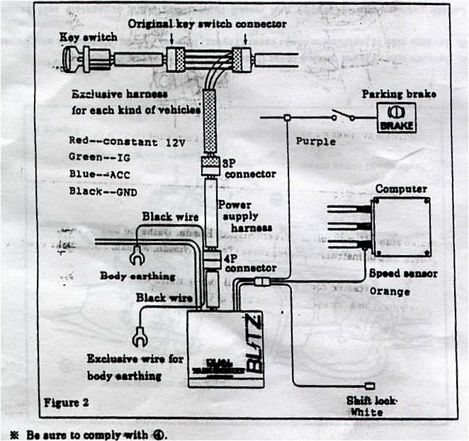
This is the basic diagram of what the install would look like (click
for a larger pic):
Here are the steps, and click on the pics below for a larger view:
Remove the panel below the steering column. There should be 4 bolt/screws
securing this panel. Once removed, the A/C duct to the driver vent should
be visible.
Either remove or set aside the A/C duct (there is 1 screw securing it).
Once that is done, you will see the steering column and a metal grate with
holes in them directly to the left of the steering column.
Remove the bolt (12 mm) and the screw securing the grate in place. They
should be located towards the top end of the grate (driver side) and the
bottom end of the grate (engine side).
Work the grate free from it's mounting place and you will see 3 harnesses
set on the grate on the backside. One of the harnesses is where you will
use the harness you have purchased. I believe that it is the one closest
to the steering wheel (the harness are of different sizes so only one of
them will fit the extra harness).
Once extra harness is clipped in, replace the metal grate as before
using the bolt and screw you removed. Do not put everyting back together
yet. You'll have to test the timer once everything is hooked up. It will
be easier and less time consuming if you should encounter a problem with
the install later.
Installation
of the Handbrake Kill Wire, ECU Wire, and AutoShift Lock Wire
This is probably going to take you a little while. It's a pain in the
ass but it's well worth it. You will need to remove the entire center section
of the interior, all the way back to the center storage box.
Handbrake
Kill Wire
Remove the cover for the center stereo console. There are 4 screws that
are covered by plastic clips. 2 are located in the top corner of the A/C
vents, and two are located in the middle of the center panel under a long
horizontal piece of plastic. Simply pop those off with a flathead screwdriver.
If a 5-speed, remove the shift knob by turning the shift knob counter-clockwise.
If it's stuck, give the knob a really big yank, it will come free. If you
have an auto, you may skip to Step 3.
Remove the panel directly below the center stereo panel you just removed.
There are 3 screws holding this down, 2 are located in the top corners
on this panel, and 1 on the ashtray area (remove the ashtray and you'll
find the screw in the top-left area). Pop the top ends on this panel off
and then slide the panel forward. you will have some wires/harness connecting
to the cigarette lighter and the mirror and suspension control switches.
Unhook those and set the panel aside.
Remove the center storage box. You'll have to empty the storage box, and
pull the carpeting of the box off. There are 5 big screws holding the box
down: 3 screws in the box and also 2 more towards the front of this entire
piece.
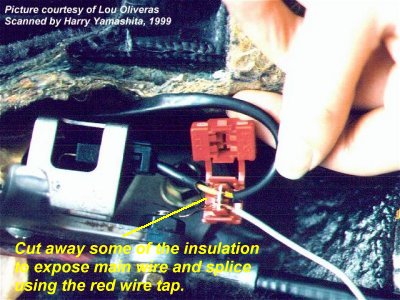
Your handbrake should now be exposed. Locate the wire to the handbrake
sensor (passenger side and toward the back of the handbrake mechanism).
You'll have to cut away some of the plastic insulation to expose the wire
AND THEN splice that wire to the purple wire of the BDTT. Here's
the diagram, this was taken from a posting on TT.net where a member wrote
that the hanbrake was optional. This is true but you will lose this feature
if you do not hook it up (basically, you'd be allowing anyone to drive
away in your while the timer is active).
Auto Shift-Lock
Wire
In the case of this wire, it is the white wire. The BDTT may not come with a wire extension for this so use any 18-20 gauge woven wire and splice them together. For the automatic
transmission Z's, you will have to find the shift lock wire that comes
off the auto shifter and splice the white wire there. As far as I know,
the autoshift lock switch is located near the base of the "gear stick"
on the stereo side.
For 5-speed/manual transmission Z's, simply ignore the white wire.
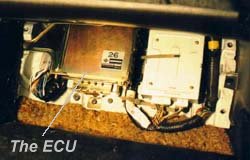
ECU Wire (Speed Sensor)
The remaining orange wire is spliced to the ECU so that it will enable
you to use the Auto-Timer feature of the BDTT. Your ECU
is located under the passenger foot board. Simply remove the carpet and
remove the wooden board. Your ECU is on the left. You'll need to remove
the ECU from it's resting position and remove the harness connecting to
the ECU. Pic of a diagram will follow, or refer to your instruction manual.
On the Japanese instruction manual, the correct diagram for Z32's ECU is
on Page 19, Diagram 3. Please look at the diagram carefully as the harness
is divided into 4 sections of 16-20-20-20 wires. The spot marked with a
black spot is the wire you will need to splice.
Once you've completed this section, find
yourself a suitable location to mount BDTT in the car. One of the more
common places is in the stock clock location. However, unlike the HKS Turbo
Timer III or IV, it's doesn't fit perfectly and you need to do some filing
to the clock opening to make the BDTT fit nicely. Also you will need to
fabricate some kind of bracket in the back to help hold the BDTT in place.
Here are some pics of alternative location
to the stock clock locations.
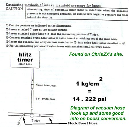
Installing
the Vacuum Boost Hose
To install this hose, you have a couple of options. If you already
have an aftermarket boost gauge already hooked up, you can simply splice
into that. Simply, cut the hose on the aftermarket boost gauge and using
the T connector (and some rubber vacuum hose, approximately 1.5 inches
on each side to ensure no boost leaks occur).
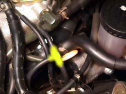
If you do not have an aftermarket boost gauge, you will have to run
the black vacuum hose (supplied with the BDTT) into the engine bay. I find
that the best way is to run the hose through the same hole as the hood
release cable. This hole is located just behind fuse area in the driver
kick panel. This will probably take some time to get the hose through as
it's a pain in the ass to get done. I would also recommend you have a metal
coat hanger handy as you will need it to be able to hook the hose from
deep in the engine bay where you're hands may not be able to get to the
hose. Once the hose the is through, you can splice the hose, using the
T connector with the hose marked below.
Testing
the Blitz Dual Turbo Timer
Remember when I told you why you shouldn't put everything back together
right away? We need to test it and see if it works first! Otherwise we'll
just end up pulling everything apart again if something goes wrong.
Test #1 Start the engine, set your timer on manual mode and set it to 20 secs
(to differentiate from auto mode). With the handbrake up, remove the key
from the ignition. Your engine should still be running and the countdown
begins. When it hit's zero, the engine should shut down.
Test #2 Start the engine, turn to auto timer mode (the timer automatically
sets it at 10 secs). Be sure there is a little square "A" on the display.
If not, the autotimer won't work in this mode. Simply push the Minute button
and the "A" will appear, push the button again to turn it off. Handbrake
up, and remove the key, timer should countdown and engine shut down at
zero.
Test #3 Set in either auto or manual mode, start the engine. With your foot
on the brake (so you won't roll away), remove the key. Timer should count
down like in the above two tests. Now with the foot on the brake, release
the handbrake anytime before the timer hits zero. The engine should automatically
shutdown.
If all of the above works fine, you have successfully completed the
install and may replace all the ducts and panels.
Enjoy
the ride!
If you should run into any problems
with the install, please email me and I will help you walk through the
installation process.
Last Updated: June 23rd,
2001.
Author: Harry Yamashita
Email: SpdDemon13@aol.com
Special thanks to Lou Oliveras
for his pictures of his install and ChrisZX for his Blitz diagrams.