Index | Ex 2-1 | Ex 2-2
Ex 2-1 Lake Cabin Walls
Lesson 2
Lake Cabin: FLOOR PLAN::
In this lesson you will get a down and dirty overview of the
functionality of Revit. We will cover the very basics of creating the
primary components of a floor plan: Walls, Doors, Windows, Roof,
Annotation & Dimensioning. Future lesions will cover these features in
more detail while learning other editing tools and such along the way.
Exercise 2-1: Walls
In this exercise we will draw the walls, starting with the exterior.
Tracing Paper Sketch of Lake Cabin Plan:
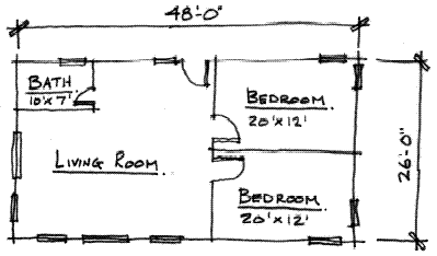
Figure 2-1 Lake Cabin Sketch

Exterior Walls:
- Start a new project named Lake Cabin.
(See lesson 1 on creating a new project.)
- Click on the Wall tool under the Basics
tab in the Design Bar (Figure 2-2).
Notice that the Options Bar has changed to show options related to walls. Next we will modify those settings.
- Modify the options bar to the following (Figure 2-3):
a. Type Selector: Click the down-arrow and select Basic: Generic – 12”.
b. Height: Change the height from 20’-0” to 9’-0”.
c. Loc Line: Set this to Finish Face : Exterior.
We are now ready to draw the exterior walls.
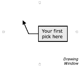
- In the Drawing Window, click in
the upper left corner.
- Start moving the mouse to the
right. Click when the wall is
48’-0” long.
Notice as you move the mouse Revit dynamically displays a length
and an angle. If you want a horizontal line you move the mouse
straight across the screen. A dashed line & a tool tip will appear
when the line is snapped to the horizontal (Figure 2-4).

If your mouse moved a little when you clicked and the wall is not
exactly 48’-0”, simply click on the dimension and type 48’ and press
enter.
You are now ready to pick the first point of your second line.

- Click the right end of the first line, making sure you snap to
the outside corner of your building. (Figure 2-5)
You may need to zoom in to pick the correct point; see Lesson 1 for zooming.
- Start moving your mouse straight down (south), while the dashed line
& tool tip appear (indicating a vertical line), type 26’ and press enter.
Typing the length allows you to accurately input a length with out having
to spend a lot of time setting the mouse in just the rightposition. However,
you can still adjust the dimension after the lineis drawn.
- Draw the other two exterior walls.
Interior Walls:
- With the Wall tool selected, modify the
options bar to the following:
a. Type Selector: Click the down-arrow
and select
Basic: Generic – 5”.
b. Loc Line: Set this to Core Centerline.
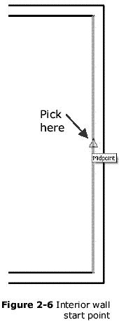
- Draw wall between bedrooms. Snap to the
midpoint of the east wall. (Figure 2-6)
- While moving the mouse to the west (left)
and snapped to the horizontal plane, type 20’2 1/2.
Note:
Type the length as shown; you don’t need a
dash or the inch symbol as they are assumed here.
You do need a space before the fraction.?>
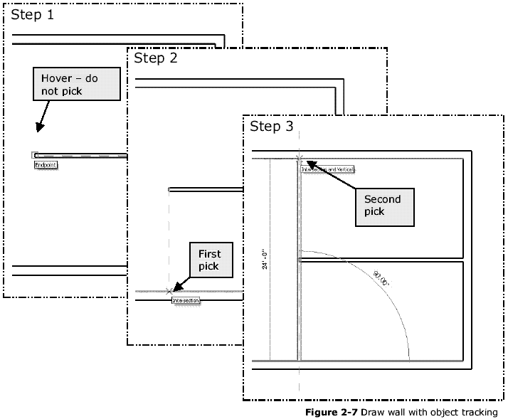
- Draw the vertical wall to close off the bedrooms. Revit allows
you to do this with one wall segment by selecting you points in
a particular way. See Figure 2-7 for a graphical description of
this process. (Figure 2-7)
- Draw the two interior walls for the bathroom to complete the interior walls. (Figure 2-1)
- Save your project.
TIP: You can use the Tape Measure tool
 to list the dimension between two points. This is helpful when you want to verify the clear dimension between walls and Revit is displaying a distance that is to the centerline of a wall. Simply click the icon and snap to two points and Revit will temporarily display the distance.
Index | ex2-1 | Ex 2-2
o0o
