0,0 _| (Using zero as the absolute location to start)
10000,0 _| (Continue with absolute co-ordinates)
10000, 8000 _|
0,8000 _|
C _| (C for Close or 0,0 _| )
Setup Screen Enviroment
LIMITS _|
0,0 _|
12000,9000 _|
GRID _|
300 _|
Z(OOM) _|
A(LL) _|
(Note: Toggle grid on and off with [F7]. Leave on.)
Commence Drawing Outside Walls
(Use the line command to draw a rectanglular outline of a floor plan)
L(INE) _| (L is the alias for line or pick ![]() or Draw->Line)
or Draw->Line)
0,0 _| (Using zero as the absolute location to start)
10000,0 _| (Continue with absolute co-ordinates)
10000, 8000 _|
0,8000 _|
C _| (C for Close or 0,0 _| )

(Now the rectangle outline is complete we start the inside of the wall)
L _| (L is the alias for line or pick ![]() or Draw->Line)
or Draw->Line)
300,300 _| (Use an absolute location to start off)
@9400, 0 _| (Now use relative x,y co-ord for a change)
@ 7400<90 _| (Now use relative polar co-ord of form M<A ie Magnitude and Angle)
@ 9400 <180 _|
C _| (C for Close or 300,300 _| or @7400<270 _| or @0, -7400 _| )

Commence Drawing Internal Walls
To create an internal wall:
L _|
MID _| ( ..for the mid point OSNAP)
Pick the mid point of the left hand side interior wall.
PER _| ( ..for OSNAP perpendicular)
Pick the opposite side (right side) internal wall.
_| (to conclude line command)
Offset this interior wall line to give the interior wall some thickness.
O(FFSET) _| (or pick ![]() or Modify->Offset)
or Modify->Offset)
200 _|
Pick the interior wall line just created.
Pick a point above the line.
_| (to conclude )

Draw a wall to partion the top half of the floor plan
L _|
Hold down the Shift key and right click in the drawing area to bring up the context menu. Select Midpoint and pick the mid point of the inside leaf of the top horizontal wall.
Hold down the Shift key and right click in the drawing area to bring up the context menu again. Select Perpendicular and pick the perpendicular point on the opposing center wall below.
_| (to conclude)

Now offset this line 100 units left and right:
O _| ( O is the alias for OFFSET or pick ![]() or Modify->Offset)
or Modify->Offset)
100 _|
Pick the partition line just created.
Pick a point to the left of the line.
Pick the partition line again.
Pick a point to the right of the line.
_| (to conclude )
Erase the unneeded centre construction line:
E(RASE) _|
Pick the centre line.
_| (to conclude the erase command)

UNDO Erase and Erase Again Using Cycling
What if the center line was very hard to pick. Of course we could zoom in but it is instructive to learn to deal with difficult selecting especially when we do more advanced drawing and lines occupy the same space. Carefully UNDO until the center line is back.
We will issue the Erase command again but press the Control button at a critical moment and release it at a critical moment so that we can deliberately cycle through the possible selections several times until we get the hang of cycling before eventually accepting the selection of the center line and complete the erase command. Here we go again, slowly now!
E(RASE) _|
Press the Control button and continue to hold it down. Observe the <cycle on> message at the command line.
Pick the centre line in such a way the the cursor pick box takes in another line alongside.
Release the Control button.
Repeatedly pick in the vicinity of the centerline and it's near companion observing the dashed line indicating selection cycling between them. Stop cycling (ie picking) with the center line selected.
_| (to exit cycling mode)
_| (to conclude the erase command)
Trim Intersection Of The Internal Walls
Now trim the intersection between the two interior walls created.
TR(IM) _| (or pick ![]() or Modify->Trim)
or Modify->Trim)
Pick both lines that represent the vertical internal wall as cutting lines (to trim to).
_| (conclude selecting cutting lines)
Pick the section that is to be trimmed (highlighted in red in the figure below.
_| (conclude trimming)

TIP: If you need to zoom in order to trim, click on the zoom realtime button ![]() . AutoCAD temporarily goes into zoom mode. Left click and hold somewhere near the center of the screen holding the left button down and push the mouse cursor up the screen causing zooming in. Once you have finished the zoom process, press the Return button (or press the the Spacebar or right click or press Escape) to exit zoom realtime and AutoCAD resumes the trim command.
. AutoCAD temporarily goes into zoom mode. Left click and hold somewhere near the center of the screen holding the left button down and push the mouse cursor up the screen causing zooming in. Once you have finished the zoom process, press the Return button (or press the the Spacebar or right click or press Escape) to exit zoom realtime and AutoCAD resumes the trim command.
Save your drawing as mytut02.dwg
Create Layers For Walls
So far all drawing has been on default layer 0. We will make a layer wallint and a layer wallext and place the walls we have drawn on the layers.
LA(YER) _| ( or pick ![]() at top of thescreen in the Object Properties Toolbar to the left of the layer drop down box)
at top of thescreen in the Object Properties Toolbar to the left of the layer drop down box)

Pick New
wallint _| (name the first new layer)
Pick New
wallext _| (name the second new layer)
All the layers are default white. To assign colors to the newly created layers:
Pick White under color for the new layer wallint (opens the Select Color dialogue box shown just below).

Pick the yellow colour in Standard Colors section.
Pick OK. (exposes the Layer Manager box again)
Pick White under color for the new layer wallext (opens the Select Color box again).
Pick the green colour in Standard Colors.
Pick OK. (exposes the Layer Manager box again)
Pick OK again to close the Layer Properties Manager box.
Put The Walls On The New Layers
What we are doing is all very clunky. An experienced cad operater usually types fast with their off hand while picking with the mouse and using the most convenient of the dialogue boxes and on-screen selection options to work with great efficiency. It will come, meanwhile lets put the walls on the new layers using one of many possible possible methods.
Pick all of the 8 lines which make up the external wall
(because no command was issued the lines all have blue "grips" at the ends and mid points)
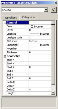
PROPERTIES _| (or pick ![]() toward the right end of the Object Properties toolbar at the top of the screen)
toward the right end of the Object Properties toolbar at the top of the screen)
Pick on the current Layer name (which is 0) and a dropdown arrow appears , pick on it and select wallext
and the selected lines of the external wall are transferred to that layer and become green.
Press Escape (de-selects the grips).
Pick each of the lines which make up the internal wall. Use Pan ![]() to pan the drawing around to aid selecting all the interior walls.
to pan the drawing around to aid selecting all the interior walls.
(they should now all all show blue grips at the ends and mid points)
Pick on the current Layer name (which is wallext) and a dropdown arrow appears, pick on it and select wallint and the selected lines of the internal wall are transferred to that layer and become yelow.
Press Escape (de-selects the grips).
If your screen is big enough some you could leave the Properties box permanently docked on the right side of the screen, but for the practice we will close it.
PROPERTIESCLOSE _| (definitely needs an alias!)
or
pick on ![]() which acts as a toggle switch and will close it,
which acts as a toggle switch and will close it,
or
Pick on the [x] at the top right of the Properties box and it will close.
Professionals with big screens (or two screens!) leave it up along with the AutoCad Design Center box (launched by the button to the left of the Properties button) docked on the left hand side of the screen. Does not leave a lot of screen left for us who scrounge in rubbish skips outside of computer shops to upgrade our systems.

Anyway your drawing should look like the image above.
if you've zoomed and panned everywhere type;
PLAN _|
or..
Z(OOM) _|
A(LL) _|
or..
Z(OOM) _|
E(XTENTS) _|
Any of the above combinations should fill the screen with your drawing.
then say..
Z(OOM) _|
0.8x _| to give 20% "white space" around the ouside.
Save As mytut03.dwg for the next tutorial
o0o