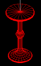
Lets make this table

The WCS will define the table base so the table has
a plan in the x,y direction of the WCS, and stands up in the z direction.
First, rotate the co-ordinate system into the vertical plane, so that you
can draw the table profile (which can be then rotated to create the table).
Rotate the UCS by 90 degrees through the x-axis
- Choose UCS from the SETTINGS Menu
- Choose or type X
- type 90
You have created a new UCS where the x-y plane is standing vertically
in the WCS, and all 2D commands will draw into this plane (in elevation).
You must now force the display to view a plan of this new UCS
- Choose PLAN from the VIEW Menu
- ENTER to accept the default
First draw a line from 0,0 to 0,800
|
Then using PLINE:
|
Start at 0,0
|
|
You've created an axis and profile to rotate around it, but first create a new layer called TABLE give it the colour 1 - RED and make it the current layer.
- From DRAW - 3D SURFS - REV SURF
- Select the PLINE for the "path curve"
- Select the first LINE as the "axis"
- Accept the following two defaults
The profile is rotated around the axis to create a 3D model. Use DISPLAY VPOINT 1,1,1 to view the model as an axonometric.
Unfortunately the resolution is not fine enough for our purposes.
Undo back until the revolution is undone. You will now alter the resolution of the REVSURF command using the surftab 1 and surftab 2 variables.
- From DRAW - 3D SURFS - REV SURF
- Choose SURFTAB 1
- Enter 20
- Select the PLINE for the "path curve"
- Select the first LINE as the "axis"
- Accept the following two defaults
The profile is rotated around the axis to create a 3D model. Use DISPLAY VPOINT 1,1,1 to view the model as an axonometric.
Save this model as L10.DWG
 This tutorial is the copyright of J. Attree
South Bank University, London UK
 Previous Page
 Menu
Menu Next Page