 Previous Page
  Menu
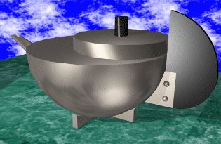
Menu Lets Make a Brandt Small Tea-Essence Pot
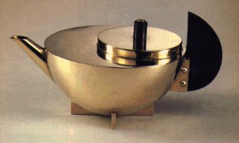
This beautiful silver tea pot from 1924 by Marianne Brandt at the
Bauhaus will serve as the model for rendering exercises later in this
course, and must be completed correctly. It was hand made from various
metals and ebony, each of which get their own layers.
Now create Silver, Steel, Ebony, as new layers, with unique colours,
and save the drawing again.
Move the origin (to create a new UCS) to just above the table top, but first save the current UCS in case you need to return to it another time.
- Choose UCS - Save
- Type ELEV1 as the name for this UCS
- Choose UCS - Origin
- Type 0,701
This create a new UCS (still in elevation) with 0,0,0 1mm above
the centre of the table, and this will allow us to create the Tea Pot.
Start by creating the bowl in a similar fasion to the table, use a PLINE
to create a profile for the bowl.
Using PLINE:
- Start at 0,0
- Type a
- d
- @1,0
- 75,75
- L
- @-75,0
Now set SILVER as the current layer, and rotate the new profile around the previous axis.
- From DRAW - 3D SURFS - REV SURF
- Select the PLINE for the "path curve"
- Select the first LINE as the "axis"
- Accept the following two defaults
The profile is rotated around the axis to create a 3D model. Use DISPLAY VPOINT 1,1,1 to view the model as an axonometric.
- Make Layer 0 the current layer, and switch OFF all of the others.
- Now OFFSET the last PLINE by 1mm to the outside
- ERASE the original PLINE.
- Draw a line from 45,-5 to @0,50
- OFFSET this line by 35mm towards the centre of the bowl

Use the last 2 lines to TRIM the profile and horizontal line, this will become one the faces of the cruciform base. Set SILVER as the current layer and:
- From DRAW - 3D SURFS - RULSURF
- Choose SURFTAB 1
- Enter 6
- Select the PLINE for the "first defining curve"
- Select the horizontal LINE as the "second defining curve"
- Move the new object 3mm up (point anywhere, then @0,0,3)
- Copy the same thing 6mm down (point anywhere, then @0,0,-6)
There is no nead to create ALL of the faces as many of them are never seen, and will only complicate the model unecessaraly. You will have to create the end face of the base, and the bottom faces would be useful to make the object complete in itself.
- Use VPOINT with 1,1,1
- ZOOM in to the base you are creating
- Use ENDpoint filters to DRAW - 3D FACE on the ends and bottom
Having made one component of the base you can now array this to create the rest in one command. But first use VIEW - PLAN with the World option, Save the current UCS as ELEV2, and UCS - Restore the World Coordinates.
- Use EDIT - ARRAY
- Choose the last 4 entities in the base using a Window
- Choose POLAR ARRAY
- Type 0,0 for the center point
- Enter 4 for the number of copies
- Accept the last 2 defaults
You will now make the bracket for the ebony handle. Set LAYER SILVER as the CURRENT LAYER.
- UCS - Restore ELEV2
- VIEW - PLAN the Current UCS
- Set LAYER 0 as the CURRENT LAYER.
- DRAW - ARC from -76,76 through 0,0 to 76,76
- DRAW - LINE from 0,85 to @100,0
- EDIT - OFFSET it down by 35mm
- DRAW - LINE from 60,0 to @0,100
- EDIT - TRIM the arc and vertical line with the horizontal lines
- Reset LAYER SILVER as the CURRENT LAYER.
- From DRAW - 3D SURFS - RULSURF
- Select the ARC for the "first defining curve"
- Select the vertical LINE as the "second defining curve"
- Move the new object 3mm up (point anywhere, then @0,0,3)
- Copy the same thing 6mm down (point anywhere, then @0,0,-6)
Now for some clever stuff with the UCS - follow carefully.
- UCS - Origin - 77,33,5
- UCS - Y axis - 90
- VIEW - PLAN - Current UCS
You should be looking at an elevation of the Tea pot with the handle
pointing out of the screen.
Now for the rivets:
- DRAW - PLINE from 0,0
- Select Arc
- Select Direction @0,1
- To @2,4
- DRAW - LINE from 0,0 to 20,0
- Set STEEL as the CURRENT LAYER
- Set SURFTAB1 to 12
- REVSRUF the PLINE around the LINE
- Accept the last 2 defaults
This rivet is quickly copied around to create all four rivet heads.
- EDIT - COPY the rivet up 15mm
- EDIT _ MIRROR the rivet in 5,0 to 5,10
Now for the ebony handle: but first we need to re-set some values.
- UCS - Restore ELEV2
- VIEW - PLAN - Current UCS
- SETTINGS - ELEV -2.5 for elevation and 5 for thickness
- LAYER - CURRENT - EBONY
- LAYER - FREEZE - SILVER
Again you will draw the outline and ask AutoCAD to create the faces
- DRAW - PLINE from 85,25
- Arc - Direction to @1,0
- To 120,60 - to 75,115
- DRAW - LINE from 75,115 to 75,25
- RULSURF from mthe PLINE to the LINE
- EDIT - COPY this surface 5mm Z direction
Now for the spout - there might be better ways of doing this
- SETTINGS - ELEVation - ELEV - 0 - THICK - 0
- SETTINGS - LAYER - CURRENT - 0
- UCS - Origin -125,75
- UCS - X axis - -90
- VIEW - PLAN - Current UCS
- DRAW - ELLIPSE - Center - 0,0
- Axis Endpoint - @8,0
- Other Axis - @0,6
- UCS - Previous
- UCS - Previous
- VIEW - PLAN - Current UCS
Change the UCS to an inclines plane, defined by three points
- UCS - 3point
- Origin Point - -45,22
- Positive X-Portion - @0,0,-10
- Positive Y-Portion - -65,48
- VIEW - PLAN - Current UCS
Draw the large ELLIPSE on this new plane
- DRAW - ELLIPSE - Axis Endpoint - 0,0
- Axis Other Endpoint- 0,35
- Other Axis - 14,17
Having set up the spout we can now ask AutoCAD to connect the two ellipses
- SETTINGS - LAYER - CURRENT - SILVER
- RULSURF between the two ELLIPSEs
Lastly the Lid:
- SETTINGS - LAYER - CURRENT - 0
- UCS - Restore - ELEV2
- DRAW - PLINE from -30,75 to -30,83 to 20,83
- DRAW - LINE from 20,83 to 20,100
- SETTINGS - LAYER - CURRENT - SILVER
- REVSURF the pline around the LINE
- Accept the next 2 defaults
And finally a small cheat for the knob on the lid
- SETTINGS - LAYER - CURRENT - EBONY
- SETTINGS - UCS - WORLD
- SETTINGS - UCS - Origin - Use ENDpoint to snap to the centre of the lid
- If the previous step is tricky first do a hide on an axonometric view
- SETTINGS - ELEV - 0 for elevation and 15 for thickness
- DRAW - CIRCLE - Centre - 0,0 - Radius - 7
So there we are, a complicated shape, but it turns out not to be too painful to model I hope. I have deliberately not chosen a building as an illustration of these tools as I want you to learn generic techniques for modelling any form, rather than tired old views of buildings.
One of the powers of CAD is that it can control curves as accurately as straight lines, I dont expect to see curvilinear objects every where, but there equally is now less restrictions to their use.
You have I hope seen how the control of the UCS allows modelling to progress more smoothly, always keeping the origin close is a good tactic.
In future weeks we will use this model as a specimen for the rendering class
if you don't get it finished today, please finish it before next week.
This tutorial is the copyright of J. Attree, South Bank University, London UK