AutoCAD Lesson 11 Part 1 Perspective Viewing & Plotting
To do this lesson you must first download a zipped AutoCAD .dwg file L11.zip (129kB zipped, expanding to 337kB unzipped).
This is part of a model created to enter an urban design competition
for Copenhagen. It was created extremely quickly and is not held up as
an example of quality modelling!
It was created at 1 unit = 1 metre
First create a layer called SCRAP, make it current, and freeze everything else except 0. You will use scrap for constrution lines and points that will eventually be frozen before the image is plotted, and layer 0 contains a rough outline of the site that will be used to create the perspectival views of model.
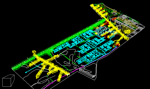
The first technique we will use is to convert an axonometric into a perspectival view.
- SETTINGS - LAYER - FREEZE - Everything Except 0
- DISPLAY - VPOINT - 3000,3000,3000
- DISPLAY - DVIEW - Select the outline
- DISTANCE - Adjust to fill the screen
The DISTANCE option fixes the cmaera target point and moves the camera
position backwards and forwards along a line from camera to target.
![]()
 Notice that the DISTANCE option in the dview command sets the image as a
perspective, and that the UCS Icon changes to a 3D box Icon indicating perspective mode.
- Press ENTER to exit DVIEW
- The screen is redrawn
- DISPLAY - VIEW - Save - Type PER1
Thaw all of the other layers to display the whole model with your new perspective view.

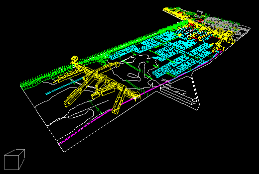
This view is useful but unexciting, it would be more dynamic with a "wide angle" perspective, and this can easily be achieved with AutoCAD
- DISPLAY - DVIEW - Previous (selects the last objects selected)
- ZOOM - Adjust to about 20mm
- DISTANCE - Adjust to about 1400
- PAN - Select in the middle of the screen
- Click again with the outline positioned in the screen
- Press ENTER to exit DVIEW
- The screen is redrawn
- DISPLAY - VIEW - Save - Type PER1 - to overwrite the view

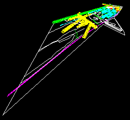
As with a camera zoom lens the use of wide angle makes the objects appear further away, hence the need to adjust the Disatnce from the camera to the target to fill the screen. The "short lens" however creates a far more dynamic view of the model. This can be taken to extremes unavailable in the physical world. Repeat the previous commands but ZOOM to a focal length of 3mm and then adjust the distance. Save this view as PER2.
 Perhaps 3mm is too short to be useful!
Create 3 more views from the other "corner" views start from -3000,3000,3000 then 3000,-3000,3000 and finaly -3000,-3000,3000. Save these views as PER3 PER4 & PER5.
An alternative and more specific method to creating a view is to place POINTs that can be snapped to for target and camera points. This method allows you to create views that exactly match a photograph taken from a known position, and monatage your new design into an existing background.
- SETTINGS - LAYER - SCRAP - CURRENT
- VIEW - PLAN - Return
- DRAW - POINT
- Type .xy (dot x y - no spaces)- Left click at 1100,1000
- This forces AutoCAD to take the x & y values from the cursor postion on screen
- You are then prompted to enter the z value Type 100
- Repeat this at 500,1000 and 0 for z
- SETTINGS - LAYER - OFF - Everything except SCRAP
- VIEW - DVIEW - Select the two points
- Type PO - NOD - Select the lefthand point
- NOD - Select the righthand point
This defines the camera and target points explicitly, the use of NODe is required to extract the x, y, & z values from the points.
- DISATNCE - Enter to accept the default distance between the two points
- ZOOM - 24 - Press ENTER to exit DVIEW
- The screen is redrawn
- SETTINGS - LAYER - ON - Everything except SCRAP
- DISPLAY - VIEW - Save - Type PER6

Finally you will alter the camera position of an existing view to create a new view.
- SETTINGS - LAYER - CURRENT - 0
- SETTINGS - LAYER - FREEZE - Everything except 0
- DISPLAY - VIEW - RESTORE - PER1
- DISPLAY - DVIEW - Select the outline
- CAmera - ENTER to fix the height of the camera
- Select an angle of about 90
As you move the mouse so the outline appears to rotate, but in fact it is you (or the camera to be precise) that is moving around the target point.
- TArget - ENTER to fix the height of the Target
- move the mouse to about -30
- PAN - Click at the far left of the screen
- Position the model centrally on screen
- You know the rest from here - exit dview - thaw the other layers - and save the view
Moving the camers is easy to control because wherever the camaera is
located it always points at the same place, normaly near the centre of
the model. Hence the model stays on screen as the camera moves.
Moving the target is more problematic. The camaera stays still but points
at a new target; in other words you stand still and pan the camera around
it is easy to see why the model often now disappears much of the time.
Save the model now! You should have saved the model at least twice
in the procedure you've just been through!
You will need these views for the next part of lesson 11 - Paper Space
and Plotting
 This tutorial is the copyright of J. Attree
South Bank University, London UK
 Previous Page
  Menu
Menu  Next Page