AutoCAD Lesson 11 Part 2
Perspective Viewing & Plotting
 Previous Page
  Menu
Menu Paper Space
Paper Space is a concept that AutoCAD uses to enable a single plot to contain a number of views of the same model. The major advantage of this is that because we use different views of the same model, as that model is altered, so all of the views are altered to reflect the changes.
Paper Space can only be utilised when TILEMODE is OFF. This is
because with tilemode on, the viewports always fill the screen completely
- they areTILED onto the screen.
When TILEMODE is OFF (or 0) we can place vports wherever we want them.
- VIEW - TILEMODE - OFF(0)
- VIEW - Paper Space
 The screen is redrawn with nothing
showing except yet another UCS Icon
indicating that we are in Paper Space.
- LAYER - NEW - PLOTTING - CURRENT
- DRAW - PLINE 0,0 - 397,0 - @0,293 - 0,293 - C
- ZOOM - Extents - ZOOM - Dynamic - move out a little
This rectangle represents an A4 sheet at 1unit=1mm, and everything we create in Paper Space will drawn at the size we want it on the paper. To be able to see the model we must create a VIEWPORT using the MVIEW command.
- VIEW - MVIEW - Create Viewport
- Click at 25,167 - and again at 186,278
A rectangle is drawn and inside the last view of the model is displayed. Viewports behave exactly like any other entity; it can be scaled, copied, moved, stretched etc.
- EDIT - COPY - Select the first viewport
- Place the copy @190,0
- VIEW - MODEL SPACE
The crosshair cursor disappears and is replaced with an arrow, until the cursor is
placed over the first viewport, when it returns to a crosshair but only in that viewport.The UCS Icon returns to the familiar icon, either perspective or orthogonal in each viewport.
Remeber that Model Space is where we create the model, and Paper Space is where we create the plot. When we are in Model Space we are back to 1unit=1metre, and we can control the view as normal. Lets restore a different saved view.
- Make sure you are in Model Space - Check the UCS Icon
- VIEW - VIEW - Restore - PER2
- Use SETTINGS - LAYER - THAW/ON as necessary
Notice that the normal layer FREEZE/THAW/ON/OFF buttons control ALL of the viewports equally, next we will see how to control layers in individual viewports
- Make sure you are in Paper Space
- VIEW - MVIEW - Click at 25,15 - and 225,145
- VIEW - MODEL SPACE to return to model space in the last viewport
- VIEW - PLAN - WORLD to get a plan of the scheme
- ZOOM - Type 0.1XP to get a scaled view
This gives a scaled plan at 1:10,000.
The ZOOM XP option (in model space) scales the model space view with respect
to the paper space units. In this case we are using 1unit=1m Model Space and 1unit=1mm Paper Space so there is already a scale factor of 1:100. the 0.1XP reduces the scale by a further factor of 10 to give 1:10,000. Adjust the layers in this viewport and return to Paper Space, and finally add some text in paper space to the drawing. Because you are working in Paper Space, on an A4 sheet, if you want 3mm high text set the height to 3 units etc.
So far so easy. But as we know AutoCAD uses Wireframe 3D models until we tell it otherwise, and this includes plotting from Paper Space. We have to explicitly set each viewport to either REMOVE or NOT REMOVE hidden lines at the time of plotting; the default is NOT to remove. Even if we set HIDE LINES in the plot Dialogue box, only the viewports set to remove the lines will do so!
- Make sure you are in Paper Space
- VIEW - MVIEW - HIDEPLOT - ON
- Select the top 2 small viewports
- FILE - PLOT - Check HIDE LINES - Pick a Window
- Select a small area of one of the 3D viewports
- Check FULL and press PREVIEW
This will give you an on-screen preview of the final plot, and if all is
well you should get a hidden line view of part of on of the viewports.
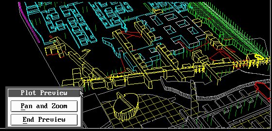
If everything is correct, you can go ahead and plot it.
Finally you should set up a single close up perspectival view the model, and plot this to a file called PLOT1 using an A4 sheet, and the Hewlet Packard Plotter. This file can then be FILE - IMPORTed into CorelDRAW where fills and bitmaps can be applied to enhance the image far beyond the scope of AutoCAD.
Now you create a simple 3D model of a detail; existing or your own design, and then create a plot from this using paper space to set out the sheet.