AutoCAD Lesson 12
Modelling Buildings
 Menu
Menu Next Page
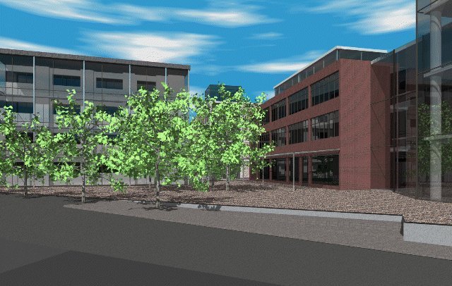
In the lesson you will build a model of this warehouse. The plan of the building (plan.dwg) is available for download as plan.zip (4kB zipped, 15kB unzipped).
The floor to floor height is 3.5m, and we will only create the model in preparation for rendering later. If you were creating the model for line drawings different techniques would be employed.
First build the columns:
- Create a layer called Column and make it current
- Set the ELEVation and THickness to 0 and 14
- Now use a PLine with a width of 0.5 and a length 0.5
- Copy this around the perimeter to create all of the columns
- Set the ELEVation and THickness to 0 and 0.5
- Now use a PLine with a width of 0.5 and draw the length of the building
The beam will have to be copied up four times by 3.5m to form the grid. You can either rotate the UCS about X through 90 or you can copy @0,0,3.5 both will have identical results.
- Create a layer called Spandrel and make it current
- Make the UCS parallel to the facade (see above) if it isnt already
- Set the ELEVation and THickness to 0 and 0
- Use 3DFACE to draw a face in the bottom left hand corner
- Make sure that it overlaps the columns and beams
- Now ARRAY the face to fill all of the bays of the facade
- Do a SHADE to check that the whole facade is filled
You must now check that the panels are in the correct plane with respect to the columns.
- Return to the WCS and do a PLAN view
- If the panels are infront or behind the columns MOVE them to the correct location
At one corner the spandrel panels are replaced with glass:
- View the facade in elevation
- Create a layer called Glass and make it current
- Use CHANGE and Window to select all of the corner panels
- Properties and LAyer will allow you to change them to layer Glass
- Do a SHADE to check that the whole facade is filled again
Above this corner a glass box is created:
- Return to a plan view and the WCS
- Set the ELEVation to 14 and THICKness to 2
- Now draw a SOLID over the glass in the corner bay
- REMEBER SOLIDs are created 1 3 2 4 otherwise you get a bow tie
You must now create the glazing bars if the model is to be believable.
- View the facade in elevation
- Create a layer called Bar and make it current
- Set the ELEVation to 0 and THICKness to .05
- Set the UCS Origin to the bottom left hand corner of any of the panels
- Using PLine Width .05 draw a rectangle just inside the the column/beam
- Now draw a cross in the middle of the panel
- Finally draw in the bars for the glass box on the roof