
Author: Kirill Yelizarov
| ! |
The Software, which you can find here, is free. I do not warrant the information or Software or results obtained by using this information, or Software. I will not be liable to you for any damages, lost savings or other consequential damages arising from your use of this information, documentation, or Software. YOU USE THIS SOFTWARE, INFORMATION, DOCUMENTATION ON YOUR OWN RISK. |
I'm receiving lots of letters about car alarm system based on PIC 12C508 Version 1.0 (link broken). The system described was introduced as a simple circuit only. I tried to focus on using one and the same pin as input and output in different situations. Parts of code were taken from my previous alarm projects (AS1 and AS2), which were a success. The code wasn't totally debugged and I have no time to revise it now. Instead, I'm introducing a new Version 1.1.
Click to view a larger picture (520Kb)
A PIC12C508 based security system is described in this project. It implements the folowing features:
Figure 1: CODE WORD TRANSMISSION FORMAT
Each pulse in a packet sets a bit in a message. Pulse width is 256 us. This pulse is modulated at 38kHz. Delay between pulses sets the bit value. Single delay (256us) means "0" bit, double delay (512us) means "1" bit, and tripple delay (768us) is a start bit. It is used to synchronise two RC generators in the main unit and in the transmitter and it shows the start of a new packet. Packets are 72 bits long. First 64 bits are password key. The last byte is divided into two nibbles. One for commands and another for CRC. Code word transmission format is shown in figure 1. It took about ~36ms (min) to ~56 ms (max) to send a message. With more than 1019 combinations and minimum delay between packets of about 110ms it will take almost 3,2*1110 years to scan the code.
Figure 2: CODE WORD ORGANIZATION
Transmitter schematic diagram is shown in figure 3.
Figure 3: TRANSMITTER SCHEMATIC DIAGRAM
![]()
Transmitter Parts List
Click to view a larger picture (76Kb)
![]()
Here you can find transmitter assembler code (updated on March 11, 2008) and a password.inc file. Don't forget to change processor type in MPLAB or you will get errors. I've added PIC16F84 family processors for debug.
Figure 4: MAIN UNIT SCHEMATIC DIAGRAM

Main Unit Parts List
Click to view a larger picture (364Kb)
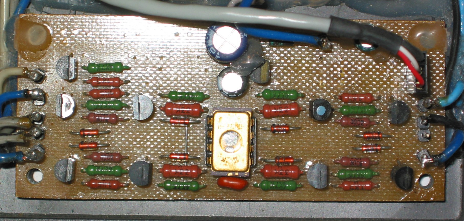
Figure 5: IR RECEIVER SCHEMATIC DIAGRAM

IR Receiver Parts List
Figure 6: IR RECEIVER SCHEMATIC DIAGRAM (TBA2800 BASED)
IR Receiver Parts List
Here you can find main unit assembler code (updated on March 11, 2008). This is a Release Candidate version 6. Don't forget to change processor type in MPLAB or you will get errors. I've added PIC16F84 family processors for debug. And here is a picture of a
test alarm (153Kb) I built using PIC16F84.
Click to view a larger picture (21Kb)
March 11, 2008
This page and all referenced files and links are copyright (c)1999-2008 Kirill Yelizarov, all rights reserved.
You can email me ykirill [AT] yahoo [DOT] com