Tracking Phase Fluctuations at COAST
If two beams from a monochromatic point source are brought together at a detector, the expectation value of the observed intensity will be:
![]() Equation 1
Equation 1
where A1 and A2 correspond to the coherent components of the complex amplitudes of
beams 1 and 2, IO is sum of the intensities of the two beams and * symbolises
complex conjugate. The phase of ![]() is equal to the phase difference between the two
light beams. Unfortunately, the
observed intensity only contains a component proportional to the real part of this
is equal to the phase difference between the two
light beams. Unfortunately, the
observed intensity only contains a component proportional to the real part of this ![]() so
that the phase cannot be directly
measured.
so
that the phase cannot be directly
measured.
In order to calculate the phase of ![]() (and hence the phase difference between the
beams), the
path length of one of the incoming light beams must be artificially modulated before the beam combining process takes place. This is
performed by adjusting the delay
lines. If the modulation applied is a constant rate of change of phase (i.e. a frequency shift),
(and hence the phase difference between the
beams), the
path length of one of the incoming light beams must be artificially modulated before the beam combining process takes place. This is
performed by adjusting the delay
lines. If the modulation applied is a constant rate of change of phase (i.e. a frequency shift), ![]() becomes a carrier-
wave. The phase of this carrier-wave reflects the phase difference between the two light beams caused by atmospheric effects. Any
fluctuations in phase difference
produced by the atmosphere will also be retained in the modulated signal -
becomes a carrier-
wave. The phase of this carrier-wave reflects the phase difference between the two light beams caused by atmospheric effects. Any
fluctuations in phase difference
produced by the atmosphere will also be retained in the modulated signal - ![]() carries
information in a similar way to a
frequency-modulated (fm) radio transmission. All the Fourier components of the fluctuations in fringe complex amplitude produced by the
atmosphere will be shifted up
in frequency, as shown schematically in Figures 4 and 5. If the frequency of the carrier-wave is greater than half of the bandwidth of the
fluctuating atmospheric signal,
it will only contain positive frequencies. The positive frequency components are transferred to the output of the light intensity detector in
the beam combining
apparatus without corruption (Figure 6). The complex conjugate of the carrier signal is also added to the observed light intensity
(Equation 1) leading to an inverted
copy of the carrier signal in the negative frequency domain. This signal can be removed, along with spurious signals created by other
atmospheric and experimental
effects, by the appropriate use of bandwidth-limiting numerical filters in the Fourier domain.
carries
information in a similar way to a
frequency-modulated (fm) radio transmission. All the Fourier components of the fluctuations in fringe complex amplitude produced by the
atmosphere will be shifted up
in frequency, as shown schematically in Figures 4 and 5. If the frequency of the carrier-wave is greater than half of the bandwidth of the
fluctuating atmospheric signal,
it will only contain positive frequencies. The positive frequency components are transferred to the output of the light intensity detector in
the beam combining
apparatus without corruption (Figure 6). The complex conjugate of the carrier signal is also added to the observed light intensity
(Equation 1) leading to an inverted
copy of the carrier signal in the negative frequency domain. This signal can be removed, along with spurious signals created by other
atmospheric and experimental
effects, by the appropriate use of bandwidth-limiting numerical filters in the Fourier domain.


Figure 4 – Power spectrum of fluctuations Figure 5 – Power spectrum of complex fringe
in the complex fringe amplitude fluctuations with phase modulation at constant rate
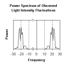
Figure 6 – Output of light intensity detector
The light intensity at the detector contains the
original carrier-wave and an inverted copy of the
carrier in the negative frequency domain.
At COAST, the average complex amplitude of the fringes during a sweep is currently estimated by looking at one Fourier component:
![]() Equation 2
Equation 2
where t is a measure of time, I(t) is intensity measured at the detectors and w r is the expected fringe frequency for a given delay line velocity and wavelength of light.
The mathematical transformation used in calculating this component:
![]() Equation 3
Equation 3
performs the same function as the local oscillator and mixer found in a superheterodyne fm radio receiver (Figure 7) or radio interferometer, where w r corresponds to the frequency of the local oscillator.

Figure 7 – Block diagram of a simple superheterodyne fm radio receiver
In the case of the radio receiver shown in Figure 7, the output VO of the filter is related to the radio-frequency input and the signal from the local oscillator in the following way:
![]()
where Viexp(i w it) is the radio- frequency input and Vrexp(i w rt) is the signal from the local oscillator. The output signal will thus be the input carrier wave shifted down in frequency by an amount w r.
This is analogous to the frequency shift
performed numerically at COAST. If the value of w
r
used in equation 3 is equal to
the frequency shift added by the motion of the delay lines, the complex amplitude of the fringes before modulation is
returned (i.e. the atmospheric component). An
alternative way of explaining this is to note that a phase change of kx was applied to
light of wavenumber k
by the offset x between the two delay lines. This phase change can be
removed by multiplying the output signal by
exp(-ikx). If the length of the delays is changing at a constant rate (i.e. the fringes are
translated at constant velocity),
kx(t) = w
rt, where
w
r is proportional to the velocity difference between the delay lines. If the delay
lines are not moving at constant velocity the transformation ![]() must be used in order to
obtain the fringe phase. It is
important to note that I’(t) is only valid as a measurement of fringe phase at times when the artificial modulation applied to
the
fringe position changes significantly faster than any atmospheric fluctuations in path length – otherwise the carrier-wave will have
negative frequency components, and
will be corrupted by the measurement process. This excludes a small number of samples at the beginning and end of each sweep, but the
effect of these erroneous
samples is easily calculable, and usually insignificant. In some instances it is best to remove the erroneous samples from the data set and
then adjust any measured
quantities in the appropriate manner.
must be used in order to
obtain the fringe phase. It is
important to note that I’(t) is only valid as a measurement of fringe phase at times when the artificial modulation applied to
the
fringe position changes significantly faster than any atmospheric fluctuations in path length – otherwise the carrier-wave will have
negative frequency components, and
will be corrupted by the measurement process. This excludes a small number of samples at the beginning and end of each sweep, but the
effect of these erroneous
samples is easily calculable, and usually insignificant. In some instances it is best to remove the erroneous samples from the data set and
then adjust any measured
quantities in the appropriate manner.
In order for I’(t) to be a useful measure of fringe complex amplitude, it must first be numerically filtered to remove unwanted components. The technique currently used for complex closure amplitude measurements involves separating data into individual sweeps, and then measuring the d.c. component in each sweep:
![]() (from equation 2)
(from equation 2)
where G is an estimation of the
average complex fringe amplitude in the sweep. This parameter is easy to calculate, and is relatively resilient to large path errors in the
incoming beam. In the Fourier
domain it represents a bandwidth-limiting filter of width ~![]() as shown in Figure 8, where
t
is the time taken for one sweep. The main drawbacks of this filter are two fold: the narrow width of the main lobe removes a
significant proportion of the signal; and the side-bands can allow noise contamination, and possibly a small amount of cross-talk between
baselines during complex
closure amplitude measurements.
as shown in Figure 8, where
t
is the time taken for one sweep. The main drawbacks of this filter are two fold: the narrow width of the main lobe removes a
significant proportion of the signal; and the side-bands can allow noise contamination, and possibly a small amount of cross-talk between
baselines during complex
closure amplitude measurements.

Figure 8 – The bandwidth filter used in complex closure amplitude measurements
Most phase measurement systems tested at COAST have used variations on this technique1. By reducing the length of the data section used to a small fraction of a sweep, the width of the filter in the Fourier domain is increased, allowing measurement of higher frequency oscillations in complex fringe amplitude. However, this type of filter is not ideally suited for phase tracking experiments. As with radio reception, a rectangular filter wide enough to incorporate both fm and am components should provide better results. This requires that the data is not split up into individual sweeps. The filtering can be performed by convolution with a suitable function of the form sinc(w t), but is most efficiently done using the Fast Fourier Transform. Examples of phase tracking experiments are shown in Section 5.
If an incoherent chromatic point source is observed, each spectral component will have a different wavelength and thus add a different Fourier component to the light intensity in the fringe envelope. With a Gaussian-shaped spectral bandwidth, a Gaussian shaped fringe envelope will be formed, such as that shown in Figure 2. These variations in the amplitude (visibility) of the fringes will be produce amplitude modulations in the carrier-wave as the fringes are scanned past the detector. Atmospheric scintillation noise can also produce additional amplitude modulations in the carrier, but neither of these effects change the phase of the fringe complex amplitude.
The parameter I’ (t) is not ideally suited to phase tracking experiments if the dominant noise source is photon shot noise. This is because the ratio of signal to photon noise is proportional to |amplitude| of the light, and not to its intensity. Unfortunately the other sources of noise which we are trying to filter from the carrier-wave are added to the light intensity rather than the amplitude, so that the numerical filtering must be performed on the intensity of the light. The best approximation I have found for the complex fringe amplitude under photon shot noise limited conditions is calculated as follows:
An approximate measure of the complex fringe amplitude is then given by:
![]()
AF takes some account of the fact that photon shot noise is greatest when the light intensity is greatest but it is still not an ideal measure of complex fringe amplitude. If the mean intensity in the incoming beams does not change with time, the signal to noise of AF will be the same as the signal to noise of I’(t). Under most observing conditions the difference between the signal to noise of AF and that of I’(t) will be negligible. I will deal only with I’(t) in the remaining sections of this report.
Care must be
taken to avoid phase-wrapping errors when the phase of I’(t) is calculated. The phase change which takes place over a short
period t, t +  t can be
calculated as:
t can be
calculated as:
 (t) =
arg(I’(t +
t)I’*(t))
(t) =
arg(I’(t +
t)I’*(t))
where arg(I’(t +
t)I’*(t))
is the phase or argument of the complex number I’(t +
t)I’*(t), and the calculated arguments should range from -
 to +
.
to +
.
If the phase of I’(t) never changes by more than
in any period of duration
t, the following iterative
procedure can be used to calculate the phase:
(t
+
t) =
(t)
+
(t)
=
(t) + arg(I’(t +
t)
I’*(t)) Equation 4
taking the starting point as:
(0) = arg(I’(0))
Return to Bob's Interferometry Page.
Return to Bob's Home Page.