Highly desirable for those who spray often, spray booths should retain spray, control overspray and exhaust fumes; without interfering with spray pattern. Size is determined by a compromise among need, allotted space and cost. Retaining spray can be accomplished by a simple cardboard box, but the other factors are greatly influenced by air current paths and velocities through the booth. These are determined by the size and shape of the enclosure; the location, size and shape of the exhaust vent and the velocity of the air currents. The combination of which can produce undesirable effects by creating swirls, recirculation or cross currents. Often these deposit overspray on painted surfaces, interfere with spray patterns and coat leveling, or leak fumes. Although it may not be obvious without testing, commonly offered booths are deficient in many critical areas, regardless of price.
Apparently from the poor designs in computer cooling and spay booth air flow, the basic principles of aerodynamics are glossed over by engineering schools or students. Currents always follow the path of least resistance and are easily influenced by surrounding conditions. In spray booths, the location, shape and force of the exhaust, the shape of the enclosure and the size and shape of the sprayed object are major factors in determining current paths. The simplest means of tracking currents visibly is to use the smoke from a lit cigarette. With the exhaust on, placing the lit end at various locations will quickly reveal the current paths toward the exhaust and any swirls and eddies. The only misleading effect is that the smoke is lighter than air and has a tendency to rise.
Examining the basic air flow in and around the booth forms the foundation for controlling and improving it. Two basic fluid dynamics principles effect movement throughout. Bernoulli stated that a current produces a surrounding vacuum effect, proportional to its velocity. Venturi added that the velocity of a current though a conduit increases as the cross sectional area decreases, to maintain constant volume flow rate. Velocity is a vector with a magnitude (speed) and direction. Acceleration is another vector, with magnitude and direction, expressing the rate of change, in either or both, the speed and direction of the velocity any point. All forces change acceleration. Since the area of the plane across booth front constricts entering currents, all factors are in effect.
With no obstructions in front of the booth, the inrush of air creates a vacuum, which draws in air from all directions in curved paths. Around the peripheral, angles of incidence to the opening plane are small, increasing toward the center to the normal or a right angle. If the booth front is set back from bench edge, the angles along the floor will be more normal to the front plane. Approaching the constricted opening, all current paths are accelerated in both speed and direction. In normal use, in the midst of the currents, a very large mobile obstruction diverts air flow; the human. Head, neck, torso, arms and hands deflect and distort paths. Fortunately, since these are somewhat rounded, and the larger parts are usually in lower velocity currents, deflections are less acute. The forces near booth entrance tend to reduce the the externally caused distortions.
Though usually insignificant in normal booth currents, the Coriolis effect, due to the earth's rotation, is quite evident in the whirlpool produced when draining a bath tub. Any disturbance in the pool of water, will easily change the shape and size of the vortex. Similar effects apply to booth currents, where other larger forces may be present.
Due to the Venturi effect, very large changes in speed and direction occur near and through the front plane. Once inside, currents are directed toward the exhaust port through devious paths determined by the environment.
Characteristics of the exhaust system are very critical to good performance. Placing the exhaust at the top, tends to lift currents, deflecting spray pattern upward and carrying overspray toward it, often directly over spayed surface. Increased velocity increases deflection and may cause an upward flow across paint surface, carrying settled overspray with it. While decreased velocity may permit overspray to settle on object from above. The jolt received upon a sudden interruption of flow or other disturbances may jar loose accumulated, dry overspray from the filter, allowing it to fall on the object. Placing the exhaust at the side eliminates fallout, but deflects currents sideways toward it, along with spray pattern and horizontal overspray, whose path may be across painted surface. Even with lipped edges, on the same surface as the exhaust, fumes may swirl from front of enclosure. The logical, optimum location is on the rear wall, where all paths will be away from both the object and open front.
Forces, produced by changing velocity magnitudes (speeds) or directions, can produce swirls, which may be large enough to effect paths. All objects, in or along the path routes, effect velocity by resistance or diversion. As almost uncontrollable elements, the objects to be sprayed and all holders deflect and divert adjacent paths, possibly creating some negative effects. On the positive side, these deflections direct overspray away from the object's edges and ends. Comparatively large, hands and forearms can also divert air flow. Even a rough surfaced wall may produce minor swirls. Higher speeds toward the rear of the sprayed surface would create a vacuum to help carry away overspray, while slower toward the front would reduce interference with spray pattern.
Dependent on the angle, the rapid change of direction in rear corners produces much larger swirls. Too frequently used, right angle corners can produce very large eddies, which can recirculate overspray back to the painted surface. Larger obtuse angles reduce the effect. Replacing intersections with large radius curves will reduce swirling greatly. Although highly impractical, to eliminate all corners and produce a constant acceleration; a truncated cone, funnel would be ideal. A truncated quadrilateral pyramid is a reasonable substitute, since corners formed by roof, sides and floor would be essentially parallel to current paths and back corner angles would be maximized. Away from rear corners acceleration would be relatively constant, producing slower speeds toward the front and faster toward the rear. With its gradually decreasing cross-sectional area, the truncated pyramid shape enhances these properties.
Turntables and solid base holders on the floor will deflect current upward, more nearly aligned with a vertically centered exhaust port. This reduces swirling problems at right angled, rear floor corner. However side deflection increases flow adjacent to side walls, increasing swirling at rear vertical corners. The ratio of the sprayed object's area to that of the booth's cross section in the same plane, effects the air flow pattern rates in direct proportion.
Size and placement of exhaust aperture at rear are important in directing paths. A small exhaust area, relative to that of the back wall, will tend to focus paths and concentrate them close to the normal at the center, which is the shortest distance, with the greatest vacuum at front. This usually directs the highest velocity paths toward the object to be painted. Along the back wall, paths will tend to be more parallel to it, causing sharper turns in corners, which increase swirling. Offsetting the opening, from center, skews the path pattern toward it, distorting spray pattern and possibly causing paths across paint surface. Enlarging the exhaust area reduces these problems. Ideally the exhaust should cover the entire back wall, with constant vacuum across the surface. This would be difficult to achieve.
Since most practical, external exhaust systems are designed to couple to standard clothes dryer ducting, they are usually driven by small circular, blade or squirrel cage fans. Some are fastened directly to a booth side, where exhaust aperture is determined by fan enclosure size; while others have flared funnel extensions to enlarge area, increasing the external clearance required. In close proximity to radial fan blades, due to the fan hub and blade contour, velocity generally increases from center outward. A larger fan, mounted on back wall, would reduce centered object diversion but increase swirling in back corners. Circular intake squirrel cage fans tend to create a vortex or whirlpool effect, which may rotate current paths into them. A long, lateral intake squirrel cage fan, oriented horizontally, with a suitably flared rectangular funnel, would provide a quasi constant pressure gradient in that direction. However, in the vertical, it would produce up or down drafts dependent on rotation direction.
To improve distribution with small fan intakes, a rectangular funnel, similar to some Hi-Fi speaker horns, can be made with baffling to control air flow. After some failed experiments, it was found that the best baffle was a centered rectangle, leaving slots around the perimeter. This directs paths toward the back wall corners with the other walls, away from object. Opposite slots should be equal for balanced directions. For offset fan centers, adjustments of flow rates should be made behind baffle to maintain equal slot balance .

Note: Adjust brightness and contrast for optimum viewing.
POOR VENT BAFFLE PLATE BASED ON DISTANCE

Note: Adjust brightness and contrast for optimum viewing.
BETTER VENT BAFFLE PLATE
Too often, to impress potential buyers, advertisements tout motor horsepower or cubic feet per minute, flow rate, which can not be converted to effectiveness in enclosure, without very extensive research. More is not necessarily better. Too much air flow at higher velocities can distort spray patterns, disturb leveling and create large eddies and swirls, which might possibly recirculate overspray and fumes. Moderation is the key. The air flow rate and velocity should be sufficient to perform the desired functions, but should not exceed this level. Since exhaust systems are rarely matched to booth characteristic's flow requirements, adjustment is desirable. In most cases this can be accomplished with an inexpensive motor speed control. Using the lit cigarette technique , the optimum rate could be established prior to spraying.
Correct lighting of the sprayed surface is crucial to a good finish. To prevent glare, bright rays should be aimed at the surface, from the front, at an angle which reflects them away from the eyes. The logical, out of the way, source location is the top, front of the booth. Several small incandescent flood lamps mounted in adjustable sockets can be hidden behind a shield plate below the top edge. The shield does not effect air flow paths in usable areas. Even with a reflector, fluorescent tubes tend to flare and do not direct rays well. Due to scattering rays, diffused light tends to hide blemishes. The touted skylights, in booth tops, provide insufficient light at the wrong angles. The heat from bulbs will be exhausted through rear vent, but may be sufficient for drying and low temperature baking with exhaust off and a cover sheet fastened across booth front opening.
Since requirements differ, probably the best way to acquire a satisfactory booth is to roll your own. Fabrication techniques are similar to those used in assembling model structures, but on a larger scale. Function rather than beauty is the requisite and without fancy windows, doors and trim; layout should be simpler than for scratch built structures. A cardboard or heavy paper, smaller scale mock-up will preview finished product and assembly methods.
Since, with the exception of motor support, stresses on the enclosure are light, thin sheets of aluminum can be used effectively. Plastic could used with cementing methods, but bending flanges is impractical without heating. Motor weight and cutout weakening, may require a heavier gauge sheet for the rear wall. Flanges can be bent upward on the side and rear floor edges to fasten walls. Roof is similar, but due to slope rear flange angle will be obtuse and a wider acute angled flange will be added for light shield.
Before rear wall layout, search for suitable surplus fans or blowers. Selling for less than $ 20 retail, many AC muffin or box fans will supply over 200 cfm and can be adapted with a little effort.
Compugate offers a 120 mm, 115 vac, 220 cfm fan for $14.95.
To actually compute the cfm required would be very difficult, but a rough idea can be estimated. A common rectangular booth W 24", H 12", D 12" would have a volume of 2 cu ft. Neglecting losses, a 200 cfm fan would replace the enclosed gas 100 times per minute. Assuming an efficiency of 50%, due to losses, the rate would be 50 times per minute or once every 1.2 seconds. This would appear to be sufficient to exhaust the most critical part of the mixture, the paint fumes. Proof is the absence of odor from thinner sprayed under normal conditions.
To aid selection visit heating and air conditioning suppliers to examine ductwork that may be adaptable. Many vents use rectangular funnels, which couple to standard 4" circular ducts. At this point, some ingenuity will be required to develop a scheme for assembly.
For external exhaust, a good quality, 4" dryer vent, with flap closure, can be mounted in a sheet of 1/8" hardboard, cut to snugly fit an ajar window opening. Edging it with neoprene combing or slit tubing will seal it, when wedged into opening. Closing widow on it will hold it in place. Using a length of flexible vent duct will ease connection and permit removal during inclement weather. With any luck, the entire assembly should cost under $100 and be far superior to those at several times the price.
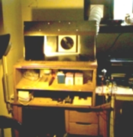
About 12 years ago for a very short time, we sold some good, one piece, plastic spray booths. Keeping the test unit, it was later installed in a spare bedroom on a small kiddy desk. Shelves were added to raise booth floor and provide storage for transient models. The booth, its very large motor and an added power switch were mounted on a sheet of plywood with a plastic, 3/4 round, outside corner molding across front, for an arm rest. A belt driven, fan blade was in a rear cavity with exhaust coupling and rectangular belt guard recess. Covering the opening, a removable frame was made to hold a new type filter. Mistakenly the new vent opening was made to duplicate the fan aperture and better support the filter. Everything seemed to work well, but later smoke tests revealed swirls in the left vertical corner, a large distance away from the off center vent.
Note: Adjust brightness and contrast for optimum viewing.
BOOTH AFTER INSTALLATION
22" X 9 1/4" X 9 1/4" deep. 12" X 8 1/4" rear wall. Angle 122.7 °.
center: poor exhaust vent.
Upper right: hardboard mounted, dryer vent in window.
Right: toaster oven.
Lower right: pantry cabinet paint storage.

Note: Adjust brightness and contrast for optimum viewing.
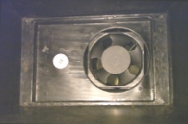
ORIGINAL REAR WALL W/ PULLEYS AND FAN
6" diameter sheet metal sleeve added to reduce leakage around blades.
Since the large motor and fan proved very noisy and inefficient, a 120 mm muffin fan was cut down to wedge fit the circular opening. After marking with opening radius, corners were cut off just outside with a bandsaw . Final trimming was done with a belt-sander and file. With a tight fit, only a small bead of fingertip rope caulk was required. Leads were fed through a grommet to speed control box. Motor and fan mount holes were closed with automotive snap-in plugs. Leftover nut, screw and washers covered large shaft hole.
Note: Adjust brightness and contrast for optimum viewing.
MODIFIED REAR WALL W/ CUT-DOWN BOX FAN
Four standoffs were made to support baffle plate and mounted to back wall of belt-way . These were made on a lathe, from 3/16" round bar stock, center drilled, bored and tapped 4-40 at both ends. These are secured to wall with lock washers to permit plate removal by removing only front screws. Less convenient, a tube can be fitted over a long screw, held with a nut. Cardboard was cut to test size required and screwed to standoffs. Optimum size proved to be that of belt guard opening, at the distance of the corner flare.


Note: Adjust brightness and contrast for optimum viewing.
TOP: VENT BAFFLE AT HORIZONTAL CENTERLINE
FRONT VENT BAFFLE
Baffle plate crosshatched
Standoffs red
Baffle strip yellow
Fan blue
Dimensions are not given, since sizes will vary.
To balance air flow horizontally, a thin strip was fastened around belt guard opening to the right of the fan centerline, reducing vent opening. This is a reasonable approximation for the air flow.
Similar to paint spraying, abrasive blasting requires a booth to retain and collect abrasive. Although spray pressures and velocities are higher, spray patterns are generally narrower and distances shorter, making retention easier. For smaller objects, provided that it is dry, the same booth may be used with lower velocity exhaust or often none, Expelled abrasive will settle to the floor of the booth, where a bag vacuum cleaner can suck it up easily for reuse. With fine sprayers such as an Air-eraser reclaimed grit should be sieved to avoid clogging.
For larger objects and guns using higher pressures, a specially designed booth is desirable. For use at high pressures and velocities with lighter abrasives, which ricochet everywhere; the enclosure is sealed. A sloped, hinged and gasketted top lid with full window, provides access, view and seal. Below in front, two holes, with sealed gloves mounted, permit hands entry for manipulation with protection. Since seal around lid perimeter may not be tight, a low volume, exhaust fan will create a vacuum to secure it. Air control is by a sprung foot valve with no regulation. Guns are frequently straight tubes with poor, uncontrolled, spray patterns. Since abrasive flow rate is normally very high, that sprayed is often collected in a hopper shaped bottom for recirculation through a siphon tube to eliminate reloading. Although often referred to as sand blasting, the very fine South Jersey sand does not cut well or rapidly. Often minute beads are used for finer finishes, but coarse grit carbides cut faster. Due to large air volumes required, at least a 2 HP compressor with large tank and regulator /moisture trap are highly desirable.
BACK TO PAINTING AND COATING
BACK TO SPRAYING ACCESSORIES
BACK TO SPRAY PAINTING
BACK TO METHODS INDEX
