Often problems arise that require extensive thought and planning with some insight of possible results. But the old empirical methods of trial and error can prove very expensive in time, labor and material. In too many cases, physically altering work during trial is not recoverable without very tedious labor. To reduce errors, scale drawings are often used to design everything from layouts through rolling stock, structures and scenery to very complex mechanical details. Drawing these with pencil and paper requires drafting skills and a lot of erasures . Accuracy is very limited to the width of a line and the ability to measure closely. Frequently many calculations are required to compute angles, curves and lengths. Computer simulations can reduce the drudgery.
A good, general purpose, Computer Aided Design (CAD) program can solve many problems before hand. Although they do not usually offer graphics for scenery and other pretty pictures, they are far more flexible. Once mastered, they can produce the most complex drawings, even in 3D. Accuracy is usually to 6 or more decimal places or one millionth of an inch or other units. Often units can be changed to metric and vice versa. Although the monitor resolution often limits the presentation, the accuracy is maintained in the data base and very exact values can be plotted and measured.
Lines, arcs, circles, polygons, fillets, dimensions, and text can produce almost any type of drafting drawing using delete-able construction points. Reference points can be located easily. Angles are set or measured accurately.
Basic sheet size and scale can be set. Viewports can select areas for enlargement of details and worked or stored separately. Layers permit overlays in different colors, for dimensions and other details, reducing clutter during drawing. Storing symbols of parts such as transistors, turnouts, crossings, screws etc. provide pasting. Individual entities or those within windowed areas can be moved, rotated or scaled easily.
Outputs can be to printer, plotter, screen images (usually GIF) and even CAM for machining. Screen images may require rendering with an image altering program. In some cases, they are transportable to other cad programs.
There are some peculiar techniques, for handling odd situations, that are learned the hard way by trial and error. Related to model railroading , some are presented below.
NOTE: Saving basic setup drawings will eliminate re-inventing the wheel.
METHODS
There is a wide variety of drawings that can prove useful. Some are simple, while others involve some head scratching. Many are interactive, but should be drawn separately to avoid clutter and permit use elsewhere . Each type has its own quirks. Those of the same type should be stored in separate directories for easy location and identification.
COUPLER MOUNTING EVALUATION
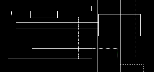
Since this is the normal working view, the drawings are made bottom side up. These consist of two parts: the coupler at the top and the car at the bottom, which is drawn first for reference. Measurements are taken from it and recorded for drawing. Coupler data can be measured or obtained from MEASURING COUPLERS .. If only horizontal measurements are required, vertical dimensions need not be to scale in most cases.
First a heavy reference line is drawn, representing the endsill or end corners, dependent on car type. Then for comparison, a dashed pulling face line is drawn parallel at the prototype distance for comparison.

Note: Adjust brightness and contrast for optimum viewing.
BACHMANN PASSENGER CAR WITH IMMOVABLE BOX
Next from the constant car measurements, the lower part of drawing is plotted. If reference is at end corner, a solid vertical, end sill line is drawn to the right at the measured distance. The required car details, such as boxes, walls, body bolsters or obstructions. are then drawn.
The box top and bottom are drawn horizontally for perspective at a convenient spacing or to scale if necessary. Box verticals will use these for trim points. Then Drawn parallel the box front edge is offset from endsill as reference for other parts. Next the dashed center post and rear added. Finally the top and bottom lines are trimmed at the front and rear.
To examine various possibilities, the upper part of drawings is different for each coupler and mounting situation. Data is derived from MEASURING COUPLERS . The upper right rectangle represents the knuckle with horn at left and important pulling face at right. The top and bottom lines are drawn horizontally ; at scale if necessary. Then the pulling face and horn are added with the known distance. Shank is added for perspective. Next a Dashed mounting center is drawn parallel to the pulling face at the mounting center distance..
Box lids may be added if used. Start with a horizontal line above shank, then using mounting center as reference draw post and mark ends. Trim to marks. If using Kadee 5 type spring, draw a line representing its rear. If the mounting center line is broken between the shank and the lower box, the entire coupler drawing can be windowed beyond the break and moved from one reference point to another. This permits trials at different setbacks.
If used, diaphragms may be added to the lower right with compressed and extended known distances from mounting surface to judge fit.
If done carefully, a preview of potential problems is presented and any distance can be measured easily. It is evident that the horn is recessed behind the end sill, which may require removal of material from bottom to clear head. The box front to mounting center distance can be measured and marked on box. Then mounted box must be trimmed back to the center post, which must be removed along with the box rear. By breaking box top and bottom line at trim points, they may be changed to dashed as a reminder of removal. Measuring the horizontal distance between the lid post and car box rear will show support requirements. Examining the spring rear shows the need for a shim support extension. Length can be measured from new box front. The post hole in it can be located.
By comparing diaphragm measurements with mounting face and coupler pulling face, a proposed selection can be made.
Before chopping into things, it is wise to verify conclusions by evaluating conditions on chosen curves. Everything may not work. If not, simply move mounting center to the new one found and try again. All this can be determined before lifting a tool.
ROLLING STOCK ON CURVES
Before designing a layout and selecting rolling stock or couplers, determining how things fit would be advisable. Plotting the necessary relationships for rolling stock on curves can be very enlightening to dispel some popular misconceptions. Positioning rolling stock on the curve can be a little tricky.
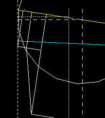
First select a sheet size that will accept the arcs of the desired radii to be drawn, long enough to handle the lengths of the equipment in question. Normally this will be about 20 °. Establish a center at the bottom of the sheet and draw an arc from 70 ° to 90 °. If both sides are necessary draw from 70 ° to 110 °. Draw a vertical reference line above the center across the arc. Zoom up to view the entire arc. Scale may be changed to a more convenient value.
For two car presentations, any of drawings may be mirrored, using the pulling face line as axis.
Using a 36" radius and a passenger car with measured values of end sill to truck center of 1.6" and 7.5" between truck centers on the track, a starting drawing is made for future use.
Inside overhang can be found by drawing a line from the track circle center through the truck center midpoint. A second line is drawn parallel to the car centerline at the half width distance. Along the radius line, measure from the track to car side line.

Note: Adjust brightness and contrast for optimum viewing.
PASSENGER CAR ON 36" RADIUS BASE DRAWING
First draw a 1.6" R circle at the pulling face track intersection. Then draw another 7.5" R at the the circle and track intersection. Draw a line Between the track intersections and extend to the pulling face line. The construction circles may be deleted. This will give an approximate location for future drawings.
KNOWN PULLING FACE TO MOUNTING CENTER DRAWINGS
To add coupler information , find Pulling face to mounting center distance from MEASURING COUPLERS.and draw a line parallel to the pulling face line at that distance.
To find the car end clearances with a given coupler, measure endsill and car half widths, end sill to end corner and mounting center to truck center distances.
The car must be repositioned to line up its mounting center with that of the coupler. This time, draw a circle with the computed mounting center to truck center radius at the centerline and mounting line intersection . From the track intersection draw another circle with truck center radius. After deleting the old centerline, connect the two track intersections with a new centerline and extend it to the pulling face line. Delete the circles.

Note: Adjust brightness and contrast for optimum viewing.
END RELATIONSHIPS
Draw a mounting center to truck center circle at the new centerline and mounting center intersection. Measure the distance between the circle and centerline to track intersections. If not less than .0001", continue to redraw the centerline. Repeat until correct.
Draw an end sill line, perpendicular to centerline, at its measured distance from mounting center. Follow this with the end corner line parallel to it at the measured distance. Next draw the endsill half width line parallel to car centerline along with the half car width. Trim the lengths to clean up view. The display will reveal problem areas and horizontal clearances can be measured. A horizontal line from the mounting center and car centerline intersection to the pulling face line will permit the coupler swing angle to be measured.
Draw a circle with the pulling face to mounting center as radius, at the mounting center. Measuring from the circle and pulling face line intersection to the end corner reference, the car separation will be twice this value.
DIAPHRAGM DRAWINGS
To try different diaphragms, again the car must be repositioned on the track. The repositioning procedure is changed slightly, by starting with the diaphragm, using its compressed, half width length. First draw a line parallel to the car centerline at the diaphragm half width distance. Next draw a face plate line perpendicular to it from the pulling face intersection to the car center line. Then draw an end sill line parallel to it at the measured, compressed diaphragm thickness. This time ,adjust the car center line as above, using the end sill intersection as reference. At this point, draw a circle with the end sill to truck center distance. Check the distance between the circle and centerline to track intersections and continue until correct.

Note: Adjust brightness and contrast for optimum viewing.
SPACING WITH DIAPHRAGMS
Next draw in the end details for perspective. Then select couplers for trial and draw their mounting center lines parallel to the pulling face line at the distances found in Measuring Couplers. Add the horizontal coupler lines to measure swing angles. Then draw the pulling face to mounting center circle and measure the spacing values from the end corner reference to circle on the car centerline.
Then the very important endsill to mounting center is measured along the car centerline. These values can be used in the coupler mounting drawings to determine problems and develop solutions.
BACK TO HOLDING
BACK TO TOOLS INDEX
