For optimum use of couplers in duplicating prototype operation and appearance, it is necessary to know the effective dimensions of both the prototype and model. For appearance sake, distances from car end references are very important; while due to sharp radii other parameters should be known. Their necessity may not be readily apparent at first, but experience will eventually prove their merit. An examination of the relevant prototype measurements precedes the evaluation of the model couplers.
Since the closest prototype couplers are the AAR type E, these will be used for comparison of those factors effecting coupling distance. Fastened on the face of the end sill, the striking plate serves as a stop for the horn, cast at the rear of the head, to prevent damage to the sill and draft gear, during pushing. The pulling face to horn (PF-H) distance is 12" with 3/8" total knuckle slack between two couplers. Draft gear springs normally keep couplers in the full pulling position. but for shock control during pushing, permit a maximum inward travel equal to the striking plate-horn (SP-H) clearance of 3". Thus the pulling face to striker distance (PF-SP) is 15", producing a striker to striker (SP-SP) distance of 30" between two cars. This will not be attainable on HO models with common drop-in couplers.
After over forty years, Kadee finally presented the horn to mounting center (mc) distance to the nearest 64th inch = .0156 = 1.36" in HO with decimal distance conversions. There appear to be some errors. Others have offered nothing. For consistent prototype distance appearance, more accurate dimensions are needed, with measuring as the solution.
The more important values relate to the pulling face and shank mounting hole, since these effect the car spacing in running trains. While pushing under heavy loads or on sharper curves, knuckles may swing out to the point where the solid part of the heads are in contact or they may misalign. Thus measured values may be used only as a comparison factor. While at rest, distances will probably be somewhere between the measured push and pull values.
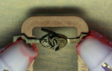
Since the pulling face location is nebulous, a more exact reference must found. The horn at the head rear is raised and easily serves as a standard reference for other measurements. The very important pulling face to horn (PF-H) can be measured using a simple jig, clamps and math. The jigs used were modified Bowser casting runners with clamping surfaces sanded flat. The clamps were cheap clothes pins with tool dip applied to reduce slipping. Sufficient but light clamping is required to permit positioning.
Two of the same type couplers are clamped to the jig, permitting knuckle movement. While coupled in a full pulling or pushing position, the horn-horn distances can be measured. Dividing by two yields the values for a single coupler. Couplers were pulled apart to the maximum, while keeping the shafts in line. Pushing required more judgement in determining the measuring point, where the knuckles just start to move sideways.
NOTE: Since it is difficult to judge the exact point at which the knuckles start to swing out during pushing. Values may not be consistently measured with identical repeated results. Therefore values and derivatives should be considered typical rather than absolute. Each value was measured 3 times and averaged.
Note: Adjust brightness and contrast for optimum viewing.
MEASURING horn-horn (original)
| COUPLER MEASUREMENTS | |||||||||||
|---|---|---|---|---|---|---|---|---|---|---|---|
| PULL | PUSH | KNUCKLE | MOUNT | SHANK | |||||||
| TYPE | horn=horn | PF-horn | horn=horn | PF-horn | SLACK | HOLE | THICK | ||||
| - | INCH | HO | INCH | HO | INCH | HO | INCH | HO | HO | INCH | INCH |
| INT | 0.387 | 33.7 | 0.194 | 16.9 | 0.366 | 31.9 | 0.183 | 15.9 | 1.82 | 0.130 | 0.0525 |
| KD 5 | 0.393 | 34.1 | 0.196 | 17.1 | 0.362 | 31.5 | 0.181 | 15.8 | 2.70 | 0.132 | 0.0535 |
| EZ II | 0.417 | 36.2 | 0.209 | 18.1 | 0.385 | 33.5 | 0.193 | 16.8 | 2.79 | 0.138 | 0.0465 |
| MH 1 | 0.420 | 36.7 | 0.210 | 18.3 | 0.377 | 32.8 | 0.189 | 16.4 | 3.74 | 0.126 | 0.0460 |
| SCALE | |||||||||||
| KD 711 | 0.287 | 25.0 | 0.144 | 12.5 | 0.234 | 20.4 | 0.127 | 10.2 | 4.62 | 0.107 | 0.0570 |
| AC | 0.298 | 26.0 | 0.149 | 13.0 | 0.274 | 23.9 | 0.137 | 11.9 | 2.09 | 0.091 | 0.0700 |
| KD 58 | 0.359 | 31.27 | 0.180 | 15.64 | 0.314 | 27.3 | 0.157 | 13.7 | 3.92 | 0.132 | 0.0540 |
| MH 41 | 0.371 | 32.3 | 0.185 | 16.2 | 0.330 | 28.7 | 0.165 | 14.4 | 3.57 | 0.126 | 0.0510 |
Note: By scanning third column PF-H, it is obvious that no coupler listed has met the 12" prototype dimension. Only the Kadee 711 came close. Although it does work with some of the others under favorable conditions, it is not generally considered in the same class.
Only Accumate Proto can meet the 30" striker-striker distance required on flats and cars with extended endsills with minor modifications.
Shaft thicknesses vary considerably, effecting vertical tolerances, tilt and sag. Kadee values include .004" for spring. Proto 2000 and others were not available.
In N scale, the Microscale (711) pf-horn is 22.5" or 10.5" too long.
MEASURING MOUNTED SPACING
Draft gear boxes effect both the pulling and pushing distances, due to play between studs and shank mounting holes. Unnecessarily, this varies drastically among couplers and boxes. Used by Athearn, Roundhouse, Varney and others, early boxes had a small square post with one or two coil springs in a shank slot similar to the prototype. To reduce the chaos, in 1958 the NMRA issued the RP-22 Universal Box, which was produced by Pacific Fast Mail. The only remnant coupler, still in production, is the Kadee #4. About that time, Athearn introduced dummy couplers with a ring hole, shank end for a 1/8" OD round stud in their new plastic passenger car kits. Kadee then followed suit with the K-5 using the present keystone shank end, along with the k-6, 7 and 8 using round ring ends. The ipso facto stud became the 1/8" round one. Due to molding draw, the base is .125" with a taper of a couple of thousands toward the tip. With an excellent idea and lack of engineering knowledge, the shank hole was set at .132; where it remains today.
Play = .132 - .125 = .007" = 1.22 hin (HO scale inches)
A very sloppy fit when compared to McHenry's .126".
Play = .126 - .125 = .001 = .087 hin.
But for forty years, it was the only game in town, if you wanted good operating couplers. These values will influence locating mounting centers.
Examining the interactive effects between boxes and couplers can help solve specific problems. Except for passenger cars, the leading edge of the box represents the striking plate and many are detailed as such.
To establish a base for comparison, a Kadee 5 box was used with all compatible couplers. Box measurements should be made, since stated values may be rounded or in error. The assemblies were clamped to the jig with trip pins clearing. Since the lip is frequently pressed against the end of the car during mounting, it is a good indicator of spacing. Since shank hole and stud diameters vary considerably and in the pulling position, the rear of the shank hole is against the rear of the stud; the pulling face to stud rear (PF-SR) will provide a standard reference for comparing shank lengths for spacing. In the pulling position, for any given stud the pulling face to mounting center (PF-MC) will be 1/2 its measured diameter toward the car end.
Measuring the lip to the stud rear or mounting center requires several steps. First the box lid is measured from front edge to rear edge with outside calipers for .462, then the depth gauge is used from rear to lip for.431". The difference yields a lip to front edge of .031" = 2.70". Next the depth from front edge to stud is measured for .187 and the lip offset subtracted.
lip to stud front (L-SF) = .187 - .031 = .156"
The more important appearance value is found by adding the measured post diameter.
lip to stud rear (L-SR) = .156 + .125 = .281"
The optimum mounting center distance (L-MC) is found by using 1/2 the stud diameter or radius.
L-MC = L-SF + .0625" = .219"
or
L-MC = L-SR - .0625" = .219"
In the table, the comparison reference, the pulling face to lip (PF-L) is 1/2 the measured lip to lip. From this the pulling face to stud rear (PF-SR) is found.
PF-SR = PF-LIP + .281" .
For later use in some cases, to find the lip to mounting center, the radius of the stud .0625" is subtracted to give L-MC = .2175" or close to 7/32", which was probably the design value.
The following apply to all coupler and box combinations, plus all types of cars.
The important pulling face to mounting center (PF-MC) is found from the lip measurements.
PF-MC = PF-LIP + L-MC
Since different types of cars will require their own spacing reference points (REF), the most important , reference to mounting center (REF-MC) must be found to locate drilled, mounting hole center. The pulling face to reference point is that found from prototype data as modified by tolerances or preferences.
REF-MC = PF-MC - PF-REF.
The remaining couplers are measured in their own boxes, since they do not fit into the #5 box. In each case, the box must be measured using methods above to ensure accuracy and determine necessary dimensions.
For Accumate Proto the front edge to lip is .016" = 1.39", the front edge to stud front is .124" and the center post is .0885".
lip to stud front (L-SF) = .124 - .016 = .108".
lip to stud rear (L-SR) = .108 + .088= .196".
L-MC = L-SF + .044" = .108 + .152".
PF-SR = PF-LIP + .196" = .199 + .196 = .395".
PF-MC = PF-LIP + .152" = .199 + .152 = .351"
For Kadee 711 the front edge to lip is .017" = 1.48", the front edge to stud front is .124" and the center post is .0925" OD for .046"R.
lip to stud front (L-SF) = .124 - .017 = .107".
lip to stud rear (L-SR) = .107 + .0925 = .1995".
L-MC = L-SF + .046" = .153".
PF-SR = PF-LIP + L-S.1995" = .207 + .1995 = .4065".
PF-MC = PF-LIP + .153" = . 207 + .153 = .360"
Push
BACK TO CLOSE COUPLING 19th CENTURY.
While measuring, the inside height should be obtained by clamping at the mounting center, using inside calipers at the front edge. Using the measured value of .073" and the shank thicknesses above, the derived clearances will shed some light on the problems in mounting, operation and their contribution to any inconsistencies in collected data below.

Note: Adjust brightness and contrast for optimum viewing.
MEASURING LIP-LIP USING KADEE 5 BOXES
Some precautions must be observed during measurement. Lips must be parallel. Calipers must pressed snugly against lips and box tops, without disturbing box positions. If errors are noted or a better method is found, please send email.
| COUPLER BOX LIP-LIP MEASUREMENTS | ||||||||||
|---|---|---|---|---|---|---|---|---|---|---|
| TYPE | PULL | PUSH | SLACK | AVERAGE | PF-SR | PF-MC | V CLR | |||
| STD | INCH | HO | INCH | HO | HO | HO | INCH | INCH | INCH | |
| KD S | 0.454 | 39.5 | 0.408 | 35.5 | 4.00 | 37.5 | 0.508 | 0.445. | 0.0185 | |
| EZ IIS | 0.484 | 42.2 | 0.448 | 39.0 | 3.10 | 40.6 | 0.523 | 0.460 | 0.0265 | |
| INT | 0.510 | 44.4 | 0.457 | 39.8 | 4.62 | 42.1 | 0.536 | 0.473 | 0.0205 | |
| KD 5 | 0.518 | 45.1 | 0.492 | 42.9 | 2.26 | 43.9 | 0.540 | 0.477 | 0.0195 | |
| KD 28 | 0.538 | 46.9 | 0.513 | 44.7 | 2.18 | 45.8 | 0.550 | 0.487 | 0.0190 | |
| MH 1 | 0.565 | 49.2 | 0.503 | 43.8 | 4.63 | 46.5 | 0.564 | 0.501 | 0.0270 | |
| EZ II | 0.568 | 49.5 | 0.498 | 43.4 | 5.83 | 46.2 | 0.565 | 0502. | 0.0265 | |
| KD L | 0.739 | 64.4 | 0.685 | 59.7 | 5.57 | 62.0 | 0.651 | 0.558 | 0.0195 | |
| SCALE | ||||||||||
| KD 58 | 0.510 | 44.4 | 0.453 | 39.5 | 5.0 | 41.9 | 0.536 | 0.473 | 0.0180 | |
| MH 41 | 0.558 | 48.6 | 0.496 | 43.2 | 5.40 | 45.9 | 0.560 | 0.497 | 0.0220 | |
| IN OWN BOX | ||||||||||
| AC | 0.398 | 34.7 | 0.375 | 32.7 | 2.0 | 33.7 | 0.395 | 0.351 | 0.0060 | |
| KD 711 | 0.414 | 36.1 | 0.335 | 28.7 | 6.9 | 32.6 | 0.406 | 0.3605 | 0.0130 | |
From the data above, it can be seen the there is a sizable variation in mounted couplers. It was noted that vertical play could cause differences greater than .010" , if not caught. This included Kadees in their own box. What can be expected with other boxes? Since this could bias results, no attempt was made to shim. Of note the EZ-II short coupler horn touched the box edge, while the Kadee short had visible clearance, in spite of Kadee's stated measurements that indicate both the coupler H-MC and box front edge to MC were 1/4". This can be attributed to the larger play between the post and shank mounting hole. On the 711, there was a large clearance in the pulling position and large slack. This is probably due the spring travel.
It might be noted that excessive slack and play contribute to jerky motions in spacings between cars. On the plus side, they might help reduce derailments, during emergency stops. Accumate Proto appears to have the least.
It would appear that slack increases with shank length with the same Kadee spring. This could be due to increased leverage, producing less centering force at the knuckles, thus resulting in misalignment.
Where they are most notable due to closer coupling, the worst cases in springing and slop are the Kadee 711 and 714. After many hours of head scratching from inconsistant results, the culprit was found to be the springing. Even though springs were installed, it was difficult to extrapolate from the large, measured excesses to operating conditions. Since the springs are at the rear, cars spread apart as load increases, making pulling position nebulous. The same condition existed in the #4 coupler, which was patially corrected by inserting a metal dowel inside the spring to limit compression.
With the large number of different draft gear boxes, both cast-on or separate, the combinations of variations are enormous and deplorable. Each application must be considered separately at assembly time. Recording the results will help with the next time around. A good data base with cell computation is invaluable.
An analysis of the relationships will reveal the problems and provide an understanding for developing possible solutions or exposing the impossible. Few boxes, if any yield correct distances. It appears that achieving both the pulling face to striker distance of 15" and the common striker to end plate of about 7" simultaneously is virtually impossible with present couplers, without recessing horns. It is clear that all vertical clearances are excessive, contributing to many mounting and operating problems. Most notable is dragging trip pins over magnets, due to sagging couplers.
In some cases, with traction or longer wheel bases on sharp curves, coupler shank swing angle may be critical. Measuring the angle is tricky. Using a protractor is difficult in both alignment and size. But using an enlarged scale drawing can help and a CAD program is better. Measure and determine half the inside front edge width and mounting center to front edge along with the half the shank width.

COUPLER RELATIONSHIPS IN BOX
To scale, draw a line for the front edge. Then draw a box centerline perpendicular to it and mark the distance from the box edge to the pivot center (PCE). On the front edge line, mark the half width of the box from the centerline. Draw a circle with a radius equal to the half shank width around the marked point. Draw a line from the pivot center, tangent to the circle. Measure the distance from the intersection of the line and the front edge to the box center line (ICL).
Swing angle = arctan ( ICL / PCE)
Use a scientific calculator or draw and measure the angle with a CAD program. The play between the coupler ring and center post is not included, since spring effects could vary it. Using this method Kadee #5 in its box yields a shank angle of about 20.6 º. N scale "T" and other shanks without fixed center point are not very amenable to this method. From the drawing, it should be noted that additional swing might be gained by trimming back the box corners. Kadee used a similar idea in the #16 coupler by combining a short #7 box with a long shank #6.
Yellow = car centerline.
White = car corner.
60' cars on 18" R w/ Kadee short couplers.
Even on an 18" R, short coupler shanks will permit pre-cushioned frame, 60' cars to run with a corner post clearance of better than .142". Even when pushing, this should provide sufficient clearance.
To use these in cast on frame boxes, the upper edge of box must be beveled with a file to clear rear of knuckle. The amount is only in the order of .040" and does not detract from appearance, if done carefully. In most cases the cover plate must be trimmed to clear.
Usually most passenger or extended striker, cushioned cars, over 60', are spaced wider in the prototype; and thus cause fewer problems in model spacing. These are discussed in Close Coupling.
BACK TO CLOSE COUPLING
BACK TO COUPLERS
BACK TO KADEE 711
BACK TO MEASURING INDEX
BACK TO METHODS INDEX
