NOTE: Pages are presented partially complete to permit use of finished data and methods. Updates will follow as car classes are developed. There should be enough projected work to keep anyone interested quite busy.
Comparing models to the prototype, increased distance between cars makes them appear dissociated and toy-like, especially on house, passenger and other high cars. Locomotives present their own problems. The distances from knuckle pulling faces to mount centers frequently yield freight car striking plate separations of 48" or more, while the prototype is closer to 30" and end plate to end plate distances exceed 56" rather than 44". Most important, for appearance on higher freight cars and vestabuled passenger cars, is the spacing between side-end corners, which varies drastically in both distance and consistency.
In spite of price and hype about following prototype measurements accurately, almost all manufacturers seem to ignore the pulling face distance from the strikers and the striker distance from the end sheets. Worse yet no consideration is given to pulling face (pf) to mounting hole or stud distance and no dimensions are given.
Admirably we have proponents for fine scale standards, who advocate that oversized flanges, tread widths and track work detract from appearance, There is a trend to produce "scale" appearing couplers for the same reason. These are worthy improvements that should be forwarded. But in actuality, how often do we see or compare these on the vast majority of layouts? Most of these can be disguised and coupler size is normally well hidden, except in closeup photos of car ends, free or coupled.
But we seemed to have overlooked that the most obvious lack of realism is car separation, standing or running. This can be seen at any distance and most angles. Looking at a distant photo, a trained eye can easily identify a train as a prototype, or even the scale of the model.
Excessive slack in knuckles and mounts produces large differences in spacing between pulling and pushing situations. Since pushing usually consists of relatively short time periods with distracting movements and varying angles or distances, separation may be less noticeable. At rest it may vary dependent on prevailing conditions. These could be disguised by avoiding broadside viewing angles. But during running, time periods are far longer and the pulling position is far more constant. Frequent quasi broadside views are often presented at advantageous viewing positions. Therefore since not all conditions can be met simultaneously, the pulling position should be selected as the compromise standard.
However the worst problem is the almost total disregard of prototype practices in cast-on draft gear boxes. In deference to erroneous concerns for clearances on sharp radii or to producing scale striker to end plate distances. None, found in HO, has achieved the correct end plate to end plate separation. Among the more common cars measured in the pulling position, only Athearn's 40' box cars with Kadee #5, approached the prototype end sheet to end sheet spacing of 43 7/8", with a possibly acceptable value of close to 45". To accomplish this, the striking plate was almost flush with the end plate. Since these cars operate well on an 18" radius, this proves close coupling can be accomplished. Inconsistently their 50' version was slightly over 50" or 6" too far. Visual verification is readily at hand by comparing blocks of each in a train on a layout.
A few example cars will show the effective problem. All cars are equipped with Kadee #5. The Athearn 40' is spaced 1 1/8" wider than the prototype.
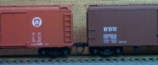
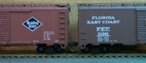
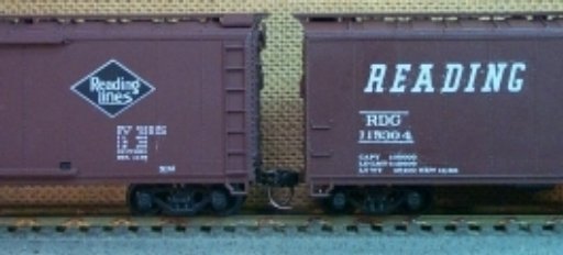
Note: Adjust brightness and contrast for optimum viewing.
SPACING COMPARISON
Red Caboose 40' Box @ 52".
Athearn 40' Box @ 45".
Athearn 50' Box @ 50".
In the broadside view, end corrugations and brake gear disguise the spacing somewhat, but bare plate ends show it clearly. At other angles the spacing is very obvious. Although not the worst cases, these illustrate the inconsistencies in coupler boxes.
Among freight cars, possibly the worst cases are flat and similar cars, where distances are judged at striking plates or endsills. It is virtually impossible to achieve correct distances on both striker and endsill simultaneously with any commonly compatible couplers, without recessing horns behind the strikers.
Passenger cars are by far the worst examples of total disregard of the apparent 30" prototype spacing at end corners. Many cases exceed 60". When compared to the prototype consistency and proximity, models appear to have been designed by a blind man or a drunkard. In too many cases, extensions to simulate diaphragms touch or overlap on curves at prototypical distances. This prevents close coupling, even without coupler considerations. It also precludes the use of working diaphragms to fill gaps. It appears that the only solution is to remove everything, back to the door jambs on heavyweights and to the end plates on lightweights.
The one evident consistency is: inconsistency prevails throughout the entire spectrum, regardless of era, car type, manufacturer, "quality" or price.
Attacking the problem requires a knowledge of the prototype distances and practices for the car's type and its era. With the wide variety of couplers available, it is mandatory to know the values of parameters which effect the distances, in order to make an optimum selection with the least effort. In too many cases, this will be next to impossible, since manufacturers have not taken these requirements into account. None has presented the requisite measurements to the degree of accuracy necessary. Even brass, super detailed RTR and high quality craftsman kits fail in this respect. It is left to the modeller to determine measurements and correct problems
A guide to developing the required model coupler data may be found in MEASURING COUPLERS
NOTE: Since house cars and passenger cars are frequently used with loading platforms, floors are set closely to standard heights. These should be used to set car height. Once set, coupler heights should be adjusted by shimming to lower or removing material at pads to raise. As often erroneously recommended , alteration at truck boss to correct coupler height could produce undesirable visual effects in both floor height and truck to body clearance.
NOTE: During mounting it would be advisable to measure box height and cut shims to reduce vertical clearance, for the coupler used, to between .002" and .005". Top or bottom position can be determined by checking with coupler height gauge and selecting that which improves height. These may be cemented in front of the posts to avoid punching holes.
Before starting massive modifications, it would be wise to establish tolerances. For the purist, exact may be demanded, but in a practical sense, this may not be achievable under present conditions. Era and car class will influence decision.
Observing and measuring some cars on track, will be enlightening and serve as a basis for the necessity of modification and the approach required. To reduce damage during measurements, plastic, inside calipers, such as General's HO Dial, should be used. Maintaining a level position, place the tips at the points dictated by class and carefully spread cars to the maximum pulling position. Avoid all projections like rivets, ladders, grabs or corrugations. Single sheath and outside braced cars should be referenced to the corner posts.
NOTE: In the General calipers used, both inside and outside tips had noticeable gaps when fully closed at zero, producing an error of about 1/2". The dial should be calibrated at some other point, by using accurately measured stock and setting dial at this value.
Since equipment and safety standards grew over the years, the era is an important factor. With different requirements, freight and non-revenue cars differed in distances from passenger cars, where open platform, vestibuled heavy weight and light weight also differed. Each group must be considered separately . First an examination of the prototype is necessary to establish a base, followed by an evaluation of the model couplers and cars, to discover the status and determine the methods to achieve optimum coupling distances. Contrary to the apparent mis-beliefs of our coupler and rollingstock manufacturers, one size does not fit all and most sizes just don't fit. Each of the two general eras and classifications will be discussed separately in the subtopics.
PROTOTYPE DEVELOPMENT
In the beginning there were no common practices. individual railroads or even a local shop foreman set their own. Without any engineering knowledge available, many varied coupling devices were copied from horse drawn wagons or developed from nightmares. As railroads extended to meet at junctions, compromise practices were negotiated to permit interchange of freight cars. Since passengers usually inconveniently changed trains at html , passenger cars often had home road peculiarities. Probably the most common, inexpensive practice consisted of bolting two large wooden blocks to end sills with a hook between them. A length of chain was strung between them with enough slack to permit negotiation of curves. This often lead to damage or derailments.
Later the link and pin was developed to remedy the situation. It consisted of a drawbar with a horizontally slotted head into which a single chain link was inserted. It was held in place by a pin, inserted through top and bottom holes. Heads, links, pins and compatibility varied widely as did height above rail. With vertical offsets, "crooked" links were offered to couple cars with different horn center heights. Sprung buffer discs were common on passenger cars, not unlike those used in Europe in later years, but closer spaced.
During the 1870's various hook type heads were developed for passenger cars. Among these were knuckle types, with the Janney emerging as the most successful . Slowly they found their way to freight cars. Some knuckles had slots and holes to accommodate links and pins. Air brakes were introduced about this time.
Car design varied widely in efforts to build a better mouse trap. Only safety considerations gradually forced some consideration of spacing. Each prototype must be evaluated for its own characteristics and spacing should be set accordingly.
By the 1890's some semblance of order developed. Eventually many older cars were converted to knuckle couplers, but still retained unnecessary buffer blocks and other features. This included some Antebellum cars.
Most models from this era can be identified by the use of truss rods. In later years these cars were generally scrapped or relegated to non-revenue service. However the truss rod, disguised wooden, CNJ Blue Comet diner Giocobini lasted until the late 1930's.
Most passenger cars sported open platforms. Except for observation cars, these later disappeared from revenue service. But in July 1950, while enroute from Chicago to Boot Camp at Great Lakes on th C & NW , I was treated to my first ride aboard a coach with open platforms , truss rods and wicker seats.
For automatic operation, use of knuckle couplers with air hoses would be believable throughout this era. However common couplers had a pulling face to horn distance of about 8 3/4"; while the shortest HO coupler, the Kadee 711, measures about 12.2". However, in most cases, available models use talgo coupler mounts with extra clearance under end sills, so the horn can be recessed under them easily. Those with cast-on boxes will require major surgery to mount Kadee 711 boxes.
For a more complete coverage of the problems and possible solutions associated with this era see: CLOSE COUPLING, 19th CENTURY.
LATER DEVELOPMENTS
During the 1890's, great changes were afoot in railroad practices, due to developments in electricity and steel. Electric street cars were replacing horse drawn ones. Electric locomotive were in the experimental stage, along with automobiles. Replacing truss rods, steel underframes were introduced, followed shortly by all steel hopper cars. Knuckle couplers, with 8 3/4" pulling face to horn, replaced link and pin. Due to the large increases in interchange, common practices were spreading. The chaos was gradually growing into a quasi standard.
Toward the turn of the century, traffic increases demanded longer trains and higher speeds. Steel underframes permitted them. As all steel cars were introduced, especially on railroads around the industrial belt, locomotive power jumped drastically and heavier couplers were needed. The newer heads had a pulling face to horn distance of 12".
Standard practice was final established with the 1910 Safety Rules. The ipso facto pulling face to striker distance was 15" or a striker to striker distance of 30". For human clearance, the spacing between end sheets or corner posts, on most freight cars, became 43 7/8" and 30" for passenger car end corners.This remained until some larger spacings were introduced with cushioned underframe cars in the latter part of the century.
No present operating knuckle coupler in HO can meet the 30" striker to striker clearance without recessing the horn into the striker. abhorrently worse, apparently no cast-on coupler box has been designed with these values or any consistency considered. For a more complete discussion, see COUPLERS/TECHNICAL EVALUATION
With some compromises, close coupling can be accomplished. Although some solutions may be relatively easy, others may require major surgery to both coupler draft gear boxes and car ends, thanks to our coupler and draft gear manufacturers.. If nothing else, reduced and consistent distances will enhance appearance drastically, to help alleviate the ludicrous, haphazard , toy like presentation.
For a more in depth coverage of the evaluation of problems and possible solutions, see CLOSE COUPLING, 1890's THROUGH MOST OF THE 20th CENTURY. If you are modelling earlier periods with truss rod cars, see CLOSE COUPLING, 19th CENTURY.
If it's not always fun, where else are challenges so diversified and rewarding?
BACK TO COUPLERS
BACK TO METHODS INDEX
