More durable for repeated and production work, and resistant to heat, metal templates or forms are used extensively to work odd shapes as well as regular ones. They are particularly useful for soldering and other heat processes. Some are flat, while others are solids, where they may be referred to as patterns. Many common items can be used; including coins, lids, bar stock, cans and almost anything handy from the kitchen to the garage. Others are specially made by cutting, carving, filing or machining. In addition to usage in fabrication and layout, many are used as gauges to check or measure items repeatedly. In a sense, even squares, miters and bevels might be considered templates.
These are probably the most common and easiest to obtain. Almost any reasonably accurate edge can be used. Thickness should be sufficient to prevent blade from overriding edge, but a very thick edge can produce waves, if blade is pressed against upper edge. The only secret to obtaining a straight line, without waves, is to ensure the cutting blade face is kept at the same angle to the edge throughout the cut.
Steel rules or scales serve well and are readily available from about 3" to 1 meter and longer. Among the more common applications, is their use as guides for cutting or scribing straight lines. Adding a length of rough surfaced tape to one side helps reduces slippage when hand holding.
Commonly found in various lengths, in the plane section of hobby shops , a TEE bar provides a convenient handle for cutting.
To hold both the edge and work piece in alignment, the guide may be fastened to the cutting backup sheet with thumb screws. Work can then be aligned and clamped in place.
Longer straight edges can be placed against rail to align track while spiking. It is easier to start by spiking ends, then the middle. Then continue spiking, about half way between the starting spikes, progressing downward at midpoints. On very long runs the edge can be slid back and forth to check progress and to correct errors while fewer spikes have been inserted.
Although not very useful as a cutting edge, hack saw and similar blades provide straight line dividers to layout rivets or equally spaced lines. Since they are sized by teeth per inch, tooth spacing can be found from the reciprocal. A 22 tpi will yield about a 4" spacing in HO. A sharp scriber or needle, placed in the VEE bottom, will establish a good straight line of reference marks. Circular blades and some gears can be used to layout arcs of rivets or radial lines for cylinder ends. Complete circles would need an arbor hole plug with center pin to align with desired center. Except for rivet counters, results are very satisfactory to the eye.
Ribbon-rail offers a series of HO and HOn3, straight and curved aligners that fit between rails nicely. They are not very convenient for laying out long stretches , where it is better to establish track centers with a trammel type tool. But they are very useful in final alignment and spiking. They are especially good at rail joint to secure proper alignment to avoid snags. Although the range of radii is wide, unfortunately the selection is limited to only even inch increments, which restricts usage on multiple, concentric curves. A 36" R curve might require a 36.5" outside curve, but none is available. Duplicates in odd sizes can be made using a trammel to scribe arcs on suitable sheet metal. The arcs would be the desired radius plus or minus half the track gauge reduced by a few thousandths for clearance.
These are quite often metal sheets shaped, drilled or tapped to measure awkward instances, where other devices are inconvenient. Most are specialized for specific usage, but your imagination can suggest other applications.
Although drill bit OD's can be measured with calipers,a gauge is more convenient. Consisting of a rectangular sheet with sized holes, annotated with dimension and size; General offers them for the common 1-60 and 61-80 numbers series bits. Use is a trial and error, go-no go process, by first trying a hole that appears to fit. If it does not, jump up a few holes or if it fits loosely jump down a few holes and try again. Once you have spanned the go and no go points, try a hole at about the middle and proceed to the middle in the direction indicated. The object is to find the smallest hole that will pass the shank.

Note: Adjust brightness and contrast for optimum viewing.
GENERAL NUMBER DRILL BIT GAUGES
1-60
61-80
NOTE: There is no standard, common sense difference between adjacent number sizes. At some points 1/2 sizes were introduced to reduce gaps between pairs.
Other series such a 1/64", letter and metric are available in machinist's catalogs.
A very similar plate, with sharper hole rims. is used to shave wooden dowels down to size.
For rough determination of hole diameters, a flat, tapered hole gauge is inserted and read at the stopping point. It has inch markings to 5/8" in 1/64" divisions on one side and metric to 15 mm in .1 mm on the other, The hole must be clear through for use.

Note: Adjust brightness and contrast for optimum viewing.
HOLE DIAMETER GAUGE
Measuring screws is a little more complicated, since also, the pitch of the threads must be found. Screw gauges have tapped holes into which screws are threaded. To complicate the issue many screw of the same diameters have different thread pitches including coarse, fine and special in the ASAE series. Additionally some metric screw are close in size and also vary in pitch (module). Care must be exercised during testing to avoid cross threading. As opposed to bits, the largest hole is the right one, as some screws have the same pitch, but different diameters.
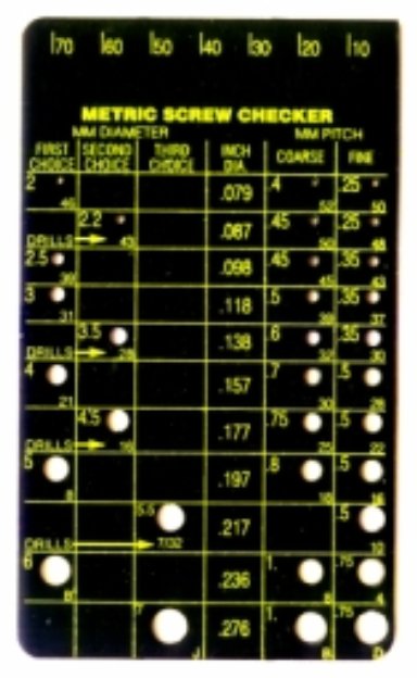
Note: Adjust brightness and contrast for optimum viewing.
METRIC SCREW GAUGE
A little large for smaller scales, this gauge covers from 2mm to 6mm. Holes on left, size tap drills and list number and fractional inch bits usable. OD is listed in inches. On right, coarse and fine threaded holes provide pitch check. Lengths are scaled at top in 10 mm increments. Similar, smaller sized gauges are easily made, if you have the tap drill bits and taps.
Nuts are measured by threading them onto known, sized screws. Here more care is needed, since they appear to fit some screws with the same pitch, but smaller diameter.
For larger screws, there are leaf types of pitch gauges with teeth that resemble saw blades. Using a back-light, these are meshed with screw threads, trying each leaf until all teeth can be seated.
NOTE:All number screw diameters are .013" apart and a #0 = .060" OD. Thus the OD can be computed easily by multiplying the number by .013" and adding .060". A #4 = .052 + .060 = .112". There is also an overlap between a #5 = .125 and a 1/8" screw. Hardware stores usually refer to them as 1/8" and many will tell you, they do not stock #5. For sizes less than #0 count the zeros, multiply and subtract.
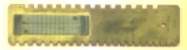
There are sheets with notches in sides for go-no go measuring of sheet material thickness. Unfortunately most are calibrated for specific metals which have differing gauge standards for specific sheet metal series such as Brown and Sharp or Stubs and not in decimal inches or millimeters.
Note: Adjust brightness and contrast for optimum viewing.
THICKNESS GAUGE w/ WIRE GAUGE
This is a jeweler's gauge with notches from 5 to 40 mm. Screwed on the face is a very fine wire or stake gauge of unknown calibration.
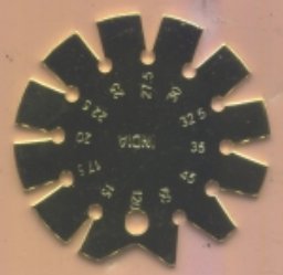
Often it is necessary to measure acute cutting or other tool angles during sharpening . Since this is usually difficult, an angle gauge can provide quick and easy checks. The bottom of VEE's has clearance to avoid contact with cutting edges.
Note: Adjust brightness and contrast for optimum viewing.
ANGLE GAUGE
Acute angles 15 to 60 degrees
Obtuse 120 °
Often overlooked and inexpensive, automotive feeler gauges can be used for measurements and setup were others will not fit. Measuring small gaps is next to impossible with calipers, but these leaves can be slid into gaps in a go-no go method to yield accurate measurements. In combination with machinist's parallels they can aid in setting cutter heights in thickness milling or planing.
A similar application was used on the Kadee coupler height gauge modification to measure pad mounting heights.

Note: Adjust brightness and contrast for optimum viewing.
FEELER GAUGE
This set runs from .0015" to .035" or .04 mm to .88 mm. Care must be used to avoid bending or breaking thinner leaves.
Occasionally it is desirable to measure concave circular arcs or fillets, but gauge sets are expensive. Often thin washers, held in a clamping handle can provide fairly close measurements.
Some are offered as multi-function gauges. Classic examples are the NMRA Standards Gauges, that check wheel and track tolerances and clearance. Using similar ideas, many useful gauges can be made.
Back in the "good old days?" when almost all car roofs were fabricated in wood, Walthers offered a passenger car, clerestory roof end, contour pattern. To use it successfully, several sheet templates were shaped to match. These were then used to check progress, while shaping ends. There was a learning curve, since there was no instruction sheet.

Note: Adjust brightness and contrast for optimum viewing.
WALTHERS PASSENGER CAR ROOF, CONTOUR PATTERN
BACK TO TEMPLATES, JIGS AND FIXTURES
