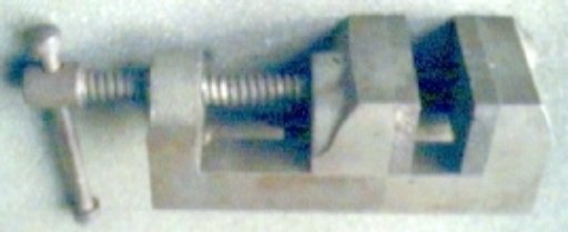
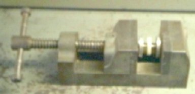
Made in the early fifty's, this very useful machinist's vise is modified to press and quarter steam loco drivers on axles. With accurate cross slots for crank pins and holes for bushings and pins, assemblies are easily held and aligned for pressing. Additional accessories were made on a lathe.
Note: Adjust brightness and contrast for optimum viewing.
Overall view of modified standard machinist's vise.
Note: Adjust brightness and contrast for optimum viewing.
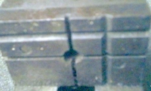
Modified faceplate.
The center hole for bushings and perpendicular crank pin slots are mirror imaged on opposite plate.
Note: Adjust brightness and contrast for optimum viewing.
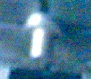
Bushing mounted in hole with wheel bore stud extended.
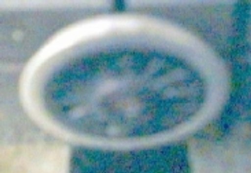
Driver mounted on stud with crank pin in slot.
Since the stud slides back in the bushing, pushed by axle during pressing, mounting is made easier by permitting pre-assembly of bushing, stud and driver. Otherwise stud might be pushed back while seating driver on already mounted stud and bushing.
Assembly ready for initial pressing.
After both drivers are mounted, axle, possibly with gears and bearings, is held between bores with needle nose pliers and slack is taken up until tips just enter driver bores. Alignment is checked for entry and pressing continues. The studs bottom in the bushings and stop pressing, short of the gauge point. This of course handles non-quartered, sans crankpin drivers and all combinations of offset gears and bearings equally well.

Final pressing at corner.
Using vise corners, final pressing is done on the hubs, positioned to avoid crank pin bosses. The vise is usually stood on end and pressing is done very slowly to avoid overshoot, while checking gauge with the NMRA Standards Gauge.

Note: Adjust brightness and contrast for optimum viewing.
Bushings, stud pins and crank pin.
Different diameter studs and bushing bores are required to match various axle diameters. Special bushings were made, with reduced end diameters to avoid pressing on crank pin bosses and a groove was cut on the side to clear closely spaced crank pins . Shown above is a specially turned crank pin, with different threads on opposite ends, which fits slots snuggly, to improve accuracy.
BACK TO QUARTERING
BACK TO DRIVER MOUNTING
BACK TO METHODS
BACK TO TOOLS INDEX
BACK TO VISES
